Pre-magnetizing device of power supply transformer and pre-magnetizing method thereof
A pre-magnetization and transformer technology, applied in circuits, magnetic objects, electrical components, etc., can solve the problems of large volume, large heat generation, inability to change voltage and phase, etc., to achieve small size, low heat generation, and medium voltage saving. The effect of switchgear
- Summary
- Abstract
- Description
- Claims
- Application Information
AI Technical Summary
Problems solved by technology
Method used
Image
Examples
Embodiment 1
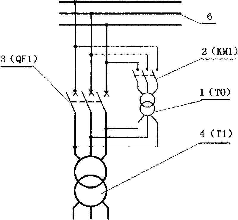
[0033] Such as figure 1 In the illustrated embodiment, the premagnetizing transformer 1 is a three-phase transformer connected in parallel with the main circuit breaker 3 at the input end of the power supply transformer 4 . This embodiment is a technical solution for pre-magnetization through the conventional main grid 6 . The pre-magnetization device can be installed in the main body of the power supply transformer on site, or in the power distribution panel. It is especially suitable for limiting the inrush current when a large transformer is put into the grid, so as to protect the grid. The power supply transformer pre-magnetization device described in this embodiment has a pre-magnetization transformer 1 for connecting with the power supply transformer 4; the input end of the pre-magnetization transformer 1 has a pre-magnetization switch device 2 for on-off , the pre-magnetized switching device 2 includes a main contact, a momentary auxiliary contact 2.1 and a time-delay...
Embodiment 2
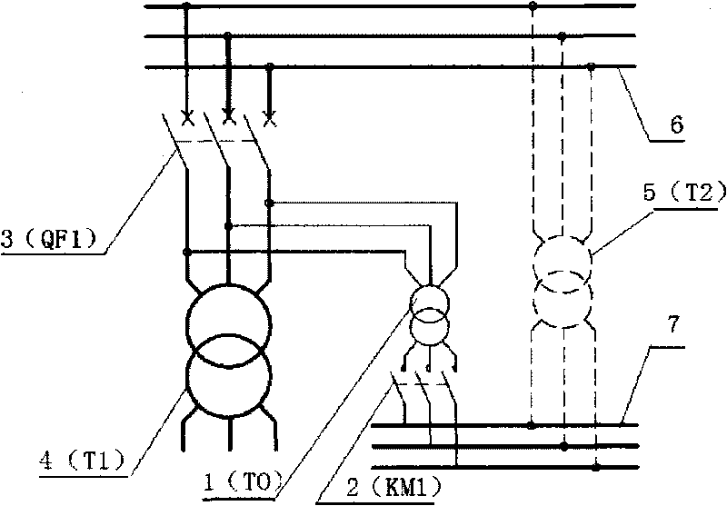
[0035] Such as figure 2 As shown, the difference from the above-mentioned embodiment 1 is: pre-magnetization schemes for different power grids. The pre-magnetizing transformer 1 is a three-phase transformer whose output end is connected to the input end of the power supply transformer, and whose input end is connected to the output end of the daily transformer 5 . The input voltage amplitude and phase of the pre-magnetizing transformer 1 are the same as those of the daily power grid 7, and the output voltage amplitude and phase are consistent with those of the main power grid 6 on the primary side of the power supply transformer 4, which is selected as 30kVA in this embodiment. The pre-magnetization time range of the pre-magnetization transformer 1 is less than or equal to 30S, which is selected as 30S in this embodiment. The capacity of the pre-magnetizing transformer can also be selected as 5kVA or 10kVA or 20kVA. The transformation ratio and connection method of the pre-...
Embodiment 3
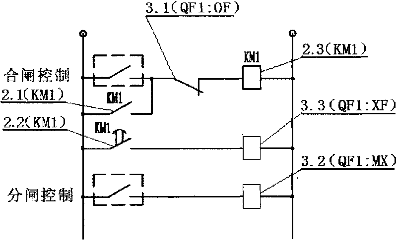
[0038] A method for pre-magnetizing a power supply transformer according to the present invention, the equipment used is the above-mentioned pre-magnetizing device, and the pre-magnetizing procedure is as follows:
[0039] 1) After receiving the closing control pulse signal of the main circuit breaker 3 at the input end of the power supply transformer 4, the pre-magnetization contactor 2 operates to start pre-magnetization;
[0040] 2), at the same time as the above step 1), the instantaneous auxiliary contact 2.1 of the pre-magnetization switch device 2 belonging to the contactor is immediately connected, and the control line package 2.3 of the self-locking pre-magnetization switch device 2;
[0041] 3), after reaching the set delay time, the delay auxiliary contact 2.2 of the pre-magnetization switching device 2 is closed, the main circuit breaker closing coil 3.3 is connected, and the main circuit breaker 3 is closed;
[0042] 4), at the same time as the above step 3), the ...
PUM
 Abstract
Description
Claims
Application Information
 - R&D
- Intellectual Property
- Life Sciences
- Materials
- Tech Scout
- Unparalleled Data Quality
- Higher Quality Content
- 60% Fewer Hallucinations
Browse by: Latest US Patents, China's latest patents, Technical Efficacy Thesaurus, Application Domain, Technology Topic, Popular Technical Reports.
© 2025 PatSnap. All rights reserved.Legal|Privacy policy|Modern Slavery Act Transparency Statement|Sitemap|About US| Contact US: help@patsnap.com


