
Current transformer

A technology of converters and fuses, which is applied in the field of converters, can solve the problems of poor electromagnetic compatibility of converters, messy cabinet layout and increased weight of converters, etc., and achieves portability, The effect of reducing design cost and reducing failure rate

Inactive Publication Date: 2010-05-05
CHINA CNR CORPORATION
View PDF0 Cites 3 Cited by
  • Summary
  • Abstract
  • Description
  • Claims
  • Application Information

AI Technical Summary

Problems solved by technology

[0003] Although the current converters in the prior art can guarantee the basic electrical performance, their external dimensions are large (2044mm*1554mm*460mm), resulting in an increase in the overall weight of the converter, and the layout of the cabinet is relatively messy, making the converter The electromagnetic compatibility of the device is not good, and failures often occur due to interference, etc.

Method used


Image

  • Current transformer
  • Current transformer
  • Current transformer

Examples


Embodiment Construction

[0022] In order to make the purpose, technical solutions and advantages of the embodiments of the present invention clearer, the technical solutions in the embodiments of the present invention will be clearly and completely described below in conjunction with the drawings in the embodiments of the present invention. Obviously, the described embodiments It is a part of embodiments of the present invention, but not all embodiments. Based on the embodiments of the present invention, all other embodiments obtained by persons of ordinary skill in the art without creative efforts fall within the protection scope of the present invention.

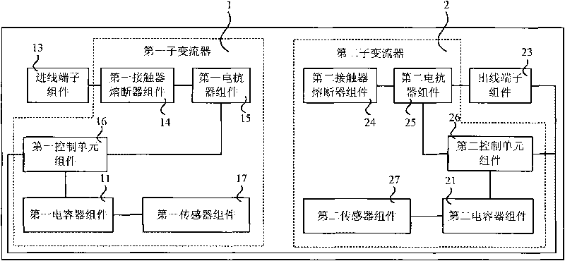
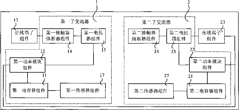
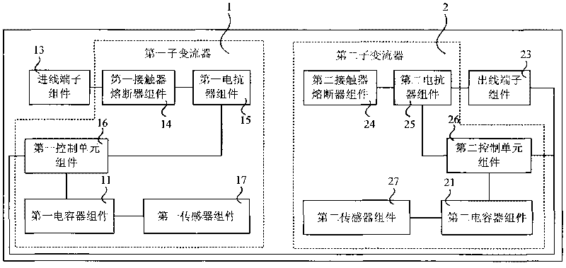
[0023] figure 1 It is a schematic diagram of the overall simplified structure of the embodiment of the converter of the present invention, such as figure 1 As shown, this embodiment provides a converter, which may specifically include a first sub-converter 1 and a second sub-converter 2 symmetrically distributed, and an incoming line terminal ass...


PUM


Abstract

The invention provides a current transformer comprising a first sub current transformer and a second sub current transformer which are in eudipleural distribution as well as an incoming terminal assembly and an outgoing terminal assembly, wherein the first sub current transformer comprises a first capacitor assembly, a first power module assembly, a first contactor fuse assembly, a first reactor assembly and a first sensor assembly which are modularly designed and arranged on the same plane and a first control unit assembly arranged above the first power module assembly; the second sub current transformer comprises a second capacitor assembly, a second power module assembly, a second contactor fuse assembly, a second reactor assembly and a second sensor assembly which are modularly designed and arranged on the same plane and a second control unit assembly arranged above the second power module assembly. The embodiment realizes modular design layout of the current transformer and reduces the external dimensions of the cabinet of the current transformer.

Description

technical field [0001] Embodiments of the present invention relate to the field of electrical technology, and in particular to a converter. Background technique [0002] With the continuous updating of light rail vehicle design, as a main part of light rail vehicle design, the requirements for traction converter are getting higher and higher. According to the requirements of the overall design of the light rail vehicle body, the traction converter is installed on the roof of the light rail vehicle, so the height of the converter is limited, and the internal structure is basically required to be laid out in the horizontal plane, so that the length and width The restrictions are also very strict, and at the same time, the requirements for high-power electrical performance and the like must be guaranteed. Therefore, great challenges are brought to the design of the converter. [0003] Although the current converters in the prior art can guarantee the basic electrical performa...

Claims


Application Information

Patent Timeline
Patent Type & Authority Applications(China)
IPC IPC(8): H02M1/00B60L1/00
Inventor 张可飞戴碧君张宇孔东晓李岩姜磊
Owner CHINA CNR CORPORATION
Learn More