Piston ring inner circle chambering machine

A piston ring and chamfering machine technology, which is applied in milling machine equipment details, metal processing equipment, milling machine equipment, etc., can solve problems such as high labor intensity, low work efficiency, and backward technology

Inactive Publication Date: 2010-05-12
仪征双环设备制造有限公司
View PDF0 Cites 5 Cited by
  • Summary
  • Abstract
  • Description
  • Claims
  • Application Information

AI Technical Summary

Problems solved by technology

The existing processing method is: the operator presses the piston ring into the chamfering mold, and feeds the knife by stepping on it. It depends entirely on the experience of the operator, and the technology is backward, which makes the labor intensity high and the work efficiency low.

Method used


Image

  • Piston ring inner circle chambering machine
  • Piston ring inner circle chambering machine
  • Piston ring inner circle chambering machine

Examples


Embodiment Construction

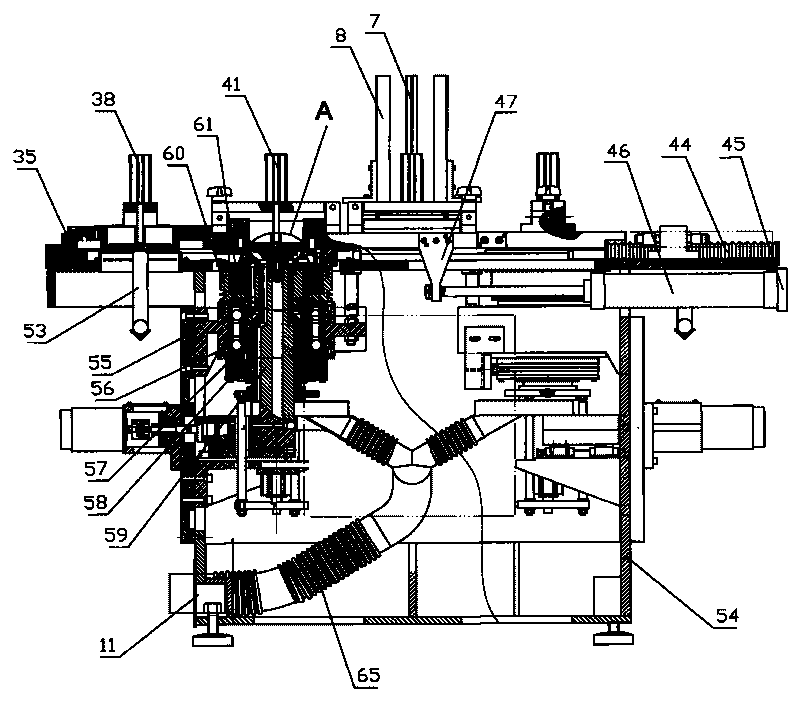
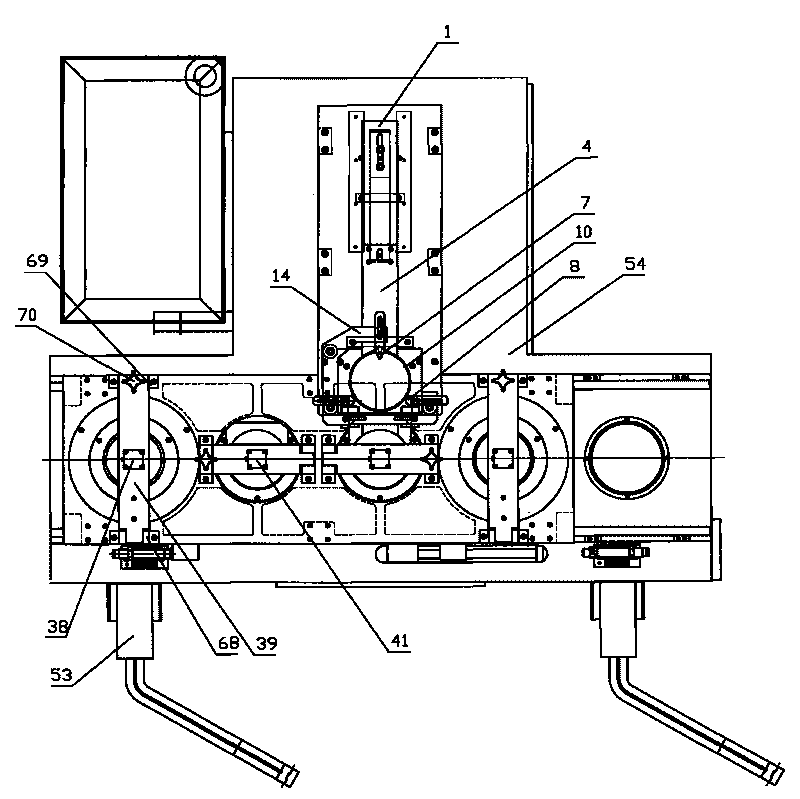
[0022] like figure 1 , 2 , shown in 5, is piston ring inner circle chamfering machine, comprises fuselage 54, and the below of fuselage 54 is symmetrically provided with two ring arrangement mechanisms 53, and each arrangement ring mechanism 53 packs support 17, fixes motor 18 on the support 17, The output shaft of motor 18 connects the ring bar 19, and the other end of the ring bar 19 connects the ring cone 20, and the ring bar 21 is set below the ring bar 19, and the support 17 is fixed on the below of the fuselage 54.

[0023] like figure 1 , 8 , 9, 10, and 11, an automatic feeding mechanism is set above the fuselage 54, the automatic feeding mechanism includes a base plate 3, the rear end of the base plate 3 is provided with a guide groove 9, and the bottom of the base plate 3 is fixed Cylinder 30, cylinder 30 is connected with piston rod support 33, and the upper end of piston rod support 33 is connected the rear end of slide plate 2 by screw 34, and slide plate 2 is a...


PUM


Abstract

A piston ring inner circle chambering machine relates to machining equipment and comprises a machine body and two ring-arranging mechanisms, wherein an automatic feed mechanism and a sliding table are arranged above the machine body; the sliding table can slide on the machine body transversely; two blanking mounting holes and two station mounting holes are arranged on the sliding table symmetrically; ring falling molds are respectively fixed above the blanking mounting holes of the sliding table; a first compression ring mechanism is arranged above each ring falling mold; charging barrels are respectively fixed above the station mounting holes; a second compression ring mechanism is arranged above each charging barrel; the machine body is internally installed with two main shafts; each main shaft is internally and coaxially provided with shaft sleeves in a penetrating way, and each shaft sleeve is sheathed with a cutter bar; each main shaft is connected with a rotary driving mechanism; the lower end of each shaft sleeve is connected with an air cylinder; the upper end of each main shaft is fixed with an electromagnetic chuck; the upper end of each electromagnetic chuck is fixed with a locating ring; each locating ring is internally provided with a ring ejection machine; the upper end of each cutter body is fixed with a cutter head, a cutter base and a cutter tool; and the left side and the right side of the piston ring inner circle chambering machine can be conducted simultaneously, and has high production efficiency.

Description

technical field [0001] The invention relates to mechanical processing equipment, in particular to the field of piston ring manufacturing. Background technique [0002] The piston ring is a non-circular metal ring with an opening, and a metal elastic ring with a large outward expansion deformation, which is assembled into the cross-section and its corresponding annular groove. After the rough machining of the piston ring, it must be chamfered inside the piston ring. The existing processing method is as follows: the operator presses the piston ring into the chamfering mold, and feeds the knife by stepping on it, which completely depends on the experience of the operator, and the technology is backward, so that the labor intensity is high and the work efficiency is low. Contents of the invention [0003] The object of the present invention is to overcome the deficiencies of the prior art and provide a piston ring internal chamfering machine, which can automatically complete ...

Claims


Application Information

Patent Timeline
IPC IPC(8): B23C3/12
Inventor 凌新连
Owner 仪征双环设备制造有限公司
Why Eureka
Try Eureka