Executor tail end quick switching mechanism

A fast switching and actuator technology, applied in the field of robots, can solve the problems of troublesome switching, long switching time, unreliable connection, etc., and achieve the effect of fast fixing and fast switching.

Inactive Publication Date: 2012-07-25
昆山市工业技术研究院有限责任公司
View PDF0 Cites 0 Cited by
  • Summary
  • Abstract
  • Description
  • Claims
  • Application Information

AI Technical Summary

Problems solved by technology

[0003] However, during the doctor’s operation, as a mechanical arm to assist the doctor’s operation, the end of the actuator often needs to switch the end auxiliary tool multiple times, and the time for each switch needs to be very short, so that the doctor can complete the operation in time and smoothly. It is required that surgical instruments can be switched easily and quickly, and can be quickly fixed. However, in the existing robotic arm system, many actuators are used to hold different surgical instruments. If different surgical instruments are used for different operations, the entire actuator needs to be replaced, which will greatly increase the cost of the system
In addition, most of the existing end tool switching devices using the same machine actuator have problems such as troublesome switching, long switching time, and unreliable connection, which greatly affects the quality and effect of doctors' operations.

Method used


Image

  • Executor tail end quick switching mechanism
  • Executor tail end quick switching mechanism
  • Executor tail end quick switching mechanism

Examples


Embodiment Construction

[0016] The present invention will be described in detail below in conjunction with the accompanying drawings.

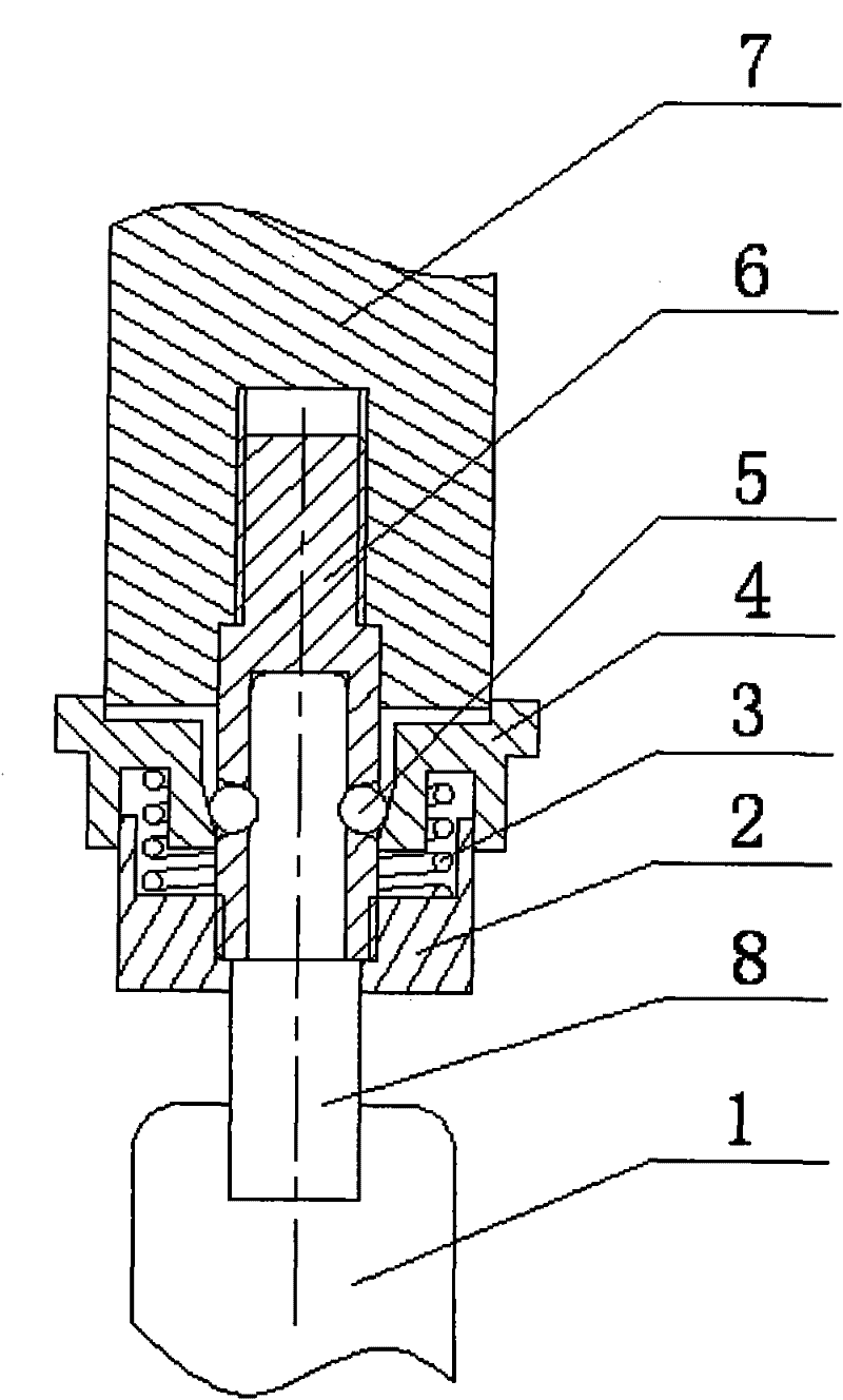
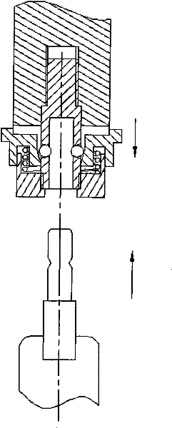
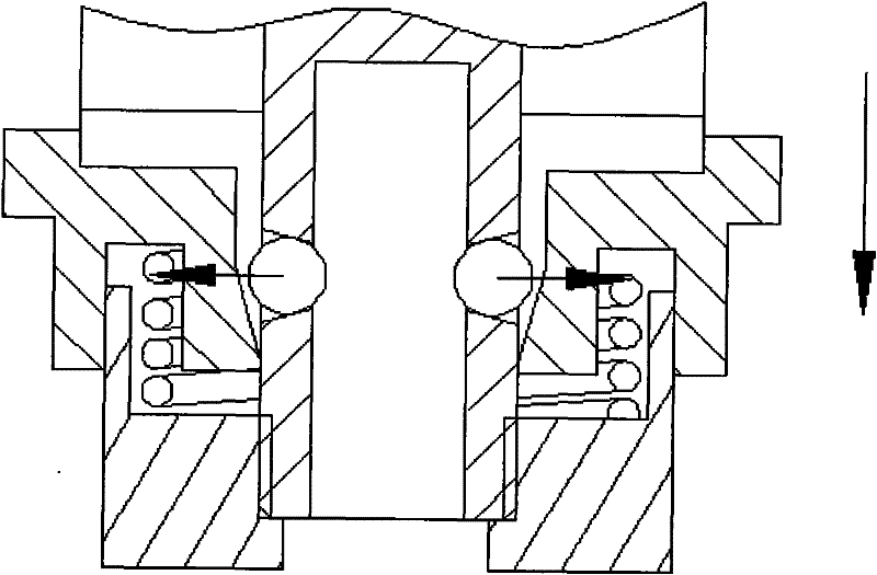
[0017] figure 1 is a sectional view of the present invention; figure 2 is the installation diagram of the present invention; image 3 It is a schematic diagram of the movement mode of the ball.

[0018] As shown in the figure, the fast switching mechanism at the end of the actuator of the present invention includes a handle 7, a central shaft 6, a spring 3, a sleeve 4 and a ball 5, and an inner hole is provided at the bottom of the handle 7, and the central shaft 6 is fixedly connected with the thread, The bottom of the central axis 6 is provided with an inner hole, and the side wall of the inner hole is provided with a transparent ball hole, and the ball 5 is installed in the ball hole.

[0019] The ball hole adopts a tapered hole, and the outer wall aperture is larger than the inner wall aperture, that is, the outside is large and the inside is small. And the ...


PUM


Abstract

The invention relates to an executor tail end quick switching mechanism. The bottom of a handle is connected with a centre shaft; an inner hole is preserved at the lower part of the centre shaft; tapered ball holes are preserved on the wall of the inner hole; the aperture of the outer wall of the inner hole is greater than that of the inner wall; the diameter of a ball is less than the aperture of the outer wall and is greater than the aperture of the inner wall; the outer side of the centre shaft is sleeved with a sleeve; the lower part of the inner wall of the sleeve is a tapered surface ofwhich an inner diameter of an upper side is greater than that of a lower side and which is matched with the ball; the lower surface of the sleeve is provided with a U-shaped groove; a spring baffle is connected to the lower end of the centre shaft through screw thread; a spring is arranged in the U-shaped groove and is encapsulated between the spring baffle and the sleeve; and a plurality of tapered holes are circumferentially preserved on the outer surface of a connecting element at the upper part of a tail-end appliance. The executor tail end quick switching mechanism is reset by means of the spring, can realize the radial movement of the balls in the tapered holes of the centre shaft through the tapered surface machined on the inner surface of the sleeve, simultaneously realize the circumferential and axial fixation of the tail-end appliance by means of the balls and realize quick switching and quick fixation, and can be applied to a plurality of surgical instruments.

Description

technical field [0001] The invention relates to a switching device, in particular to a fast switching mechanism at the end of an actuator used for quickly installing different surgical instruments on a mechanical arm of minimally invasive surgery such as surgery, and belongs to the field of robot technology. Background technique [0002] In minimally invasive surgery, multiple assistants are required to forcefully open the incision to poke the patient's internal organs. However, we know that surgical operations generally take a long time, and surgical personnel are prone to fatigue, which can easily cause incisions to not be properly opened, and internal organs and lesions cannot be well isolated, so that it will seriously affect the doctor's surgical field of view and operation. . Therefore, in minimally invasive surgery, the surgical auxiliary robot arm is used to assist the surgeon to complete the minimally invasive surgery. The surgical auxiliary robot arm is mainly use...

Claims


Application Information

Patent Timeline
Patent Type & Authority Patents(China)
IPC IPC(8): B25J19/00A61B17/00
Inventor 王峰唐粲李超程胜张建伟
Owner 昆山市工业技术研究院有限责任公司
Why Eureka
Try Eureka