Mechanical continuous variable valve lift driving device

A valve lift and driving device technology, applied in the direction of valve devices, mechanical equipment, machines/engines, etc., can solve the problems of increasing fuel consumption and pumping loss of the whole machine, so as to reduce fuel consumption, reduce pumping loss and improve power performance Effect

Active Publication Date: 2010-05-12
SAIC MOTOR
View PDF0 Cites 12 Cited by
  • Summary
  • Abstract
  • Description
  • Claims
  • Application Information

AI Technical Summary

Problems solved by technology

Taking a gasoline engine as an example, when the load is small, only a small amount of air is needed, and in order to prevent excess air fro

Method used


Image

  • Mechanical continuous variable valve lift driving device
  • Mechanical continuous variable valve lift driving device
  • Mechanical continuous variable valve lift driving device

Examples


Embodiment Construction

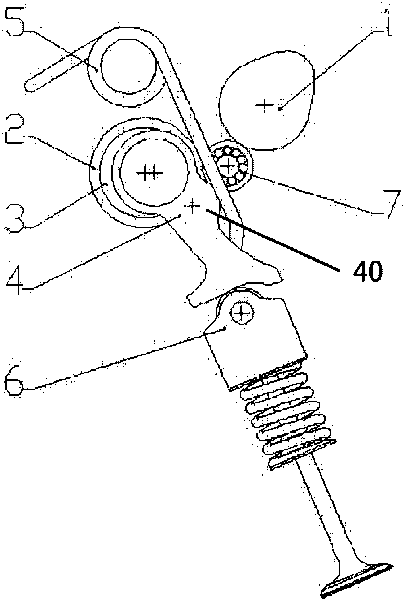
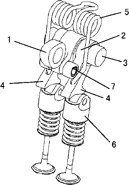
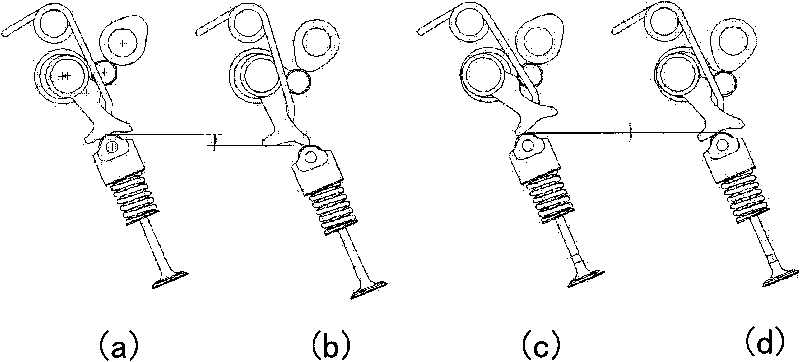
[0018] Such as figure 1 with figure 2 As shown, the mechanical continuously variable valve lift driving device of the present invention is used to drive a tappet type valve spring assembly or a rocker arm type valve spring assembly with a special profile as a valve lift-opening continuous continuously adjustable solution.

[0019] The mechanical continuously variable valve lift driving device of the present invention includes a swing arm 4, a rocker arm 2, a control shaft 3, a cam 1 and a return spring assembly 5. The swing arm 4 is installed on the control shaft 3 and can be wound around the control shaft 3 Reciprocating swing, the end face of the far end of the swing arm 4 relative to its swing fulcrum (i.e. the control shaft 3) is a cam profile, which is used to interact with the valve spring assembly 6. The arc surface of the center of the circle (the base circle segment) and at least one section of the function arc surface (working section), the function arc surface is...


PUM


Abstract

The invention provides a mechanical continuous variable valve lift driving device comprising a swing arm, a rocker arm, a cam shaft and an offset spring, wherein the swing arm swings by taking a first supporting seat as a fulcrum; the rocker arm swings by taking a second supporting seat as a fulcrum, the second supporting seat is a movable supporting seat; when the cam shaft rotates, a cam of the cam shaft is acted on the rocker arm to lead the rocker arm to swing, and the rocker arm is simultaneously acted on the swing arm to lead the swing arm to swing; and an offset spring assembly provides restoring force acted on the swing arm so as to press the swing arm and the rocker arm to lean against the cam shaft. The start lift and the continuous flexible control during the duration on a valve can be realized through adjusting the second supporting seat under the control of electronic equipment, thereby lowering the oil consumption of a whole engine and improving the power performance.

Description

technical field [0001] The invention relates to an engine valve driving device. Background technique [0002] Most practical piston heat engines use valve actuation mechanisms to control the air charge into the cylinders. The mechanical parameters of the valve drive mechanism have been designed and determined, so the valve movement law is fixed and cannot be adjusted during the actual operation of the engine. [0003] The operating conditions of the engine are complex, and the demand for air charge in the cylinder varies greatly with different operating conditions. Taking a gasoline engine as an example, when the load is small, only a small amount of air is needed, and in order to prevent excess air from entering the cylinder, a throttle valve is required, which will cause pumping loss and increase the fuel consumption of the whole machine. [0004] If the lift and duration of the valve opening can be controlled, it may replace the throttle valve and play a role in control...

Claims


Application Information

Patent Timeline
IPC IPC(8): F01L13/00F01L1/18F01L1/34
Inventor 张华钱承炬郝晓伟武涛张小虎吕世亮章健勇李冲霄邵强孔毅
Owner SAIC MOTOR
Why Eureka
Try Eureka