Self-compensating constant-force spring hanger

A constant force spring, self-compensating technology, applied in the field of supports and hangers, can solve the problems of high cost, large lateral size, and difficult layout of supports and hangers, and achieve the effects of reducing production costs, symmetrical force, and compact shape.

Inactive Publication Date: 2010-05-12
高永峰
View PDF2 Cites 9 Cited by
  • Summary
  • Abstract
  • Description
  • Claims
  • Application Information

AI Technical Summary

Problems solved by technology

The large number of springs and high precision requirements make the cost of this support and hanger very high; second, this support and hanger is equipped with two auxiliary springs in the transverse direction, which makes its transverse dimension larger and saves space. Difficult to arrange in small places

Method used


Image

  • Self-compensating constant-force spring hanger
  • Self-compensating constant-force spring hanger
  • Self-compensating constant-force spring hanger

Examples


Embodiment 1

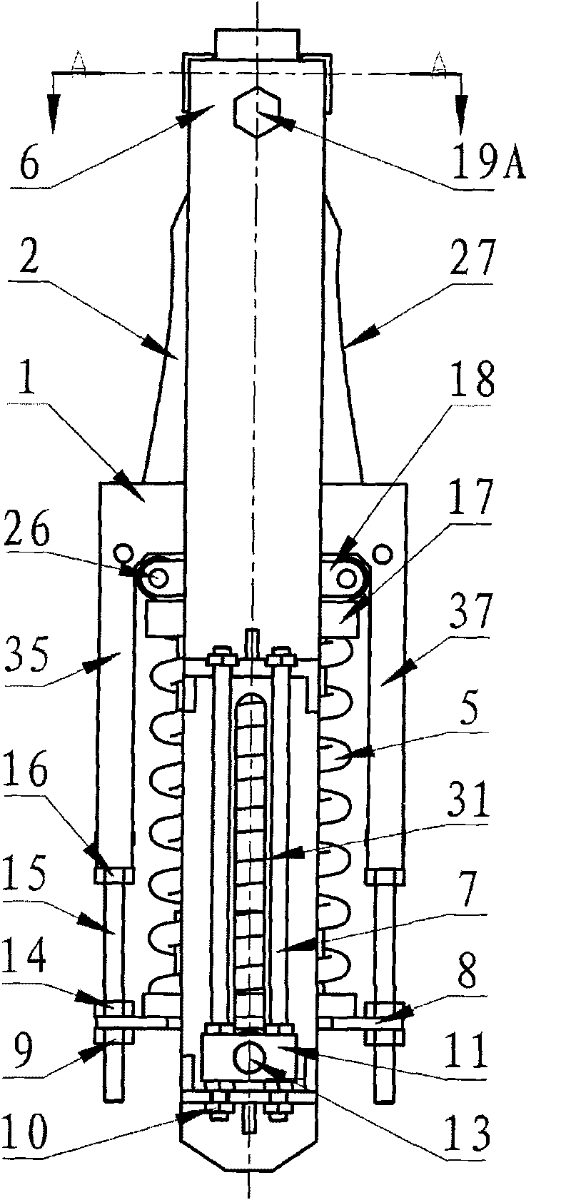
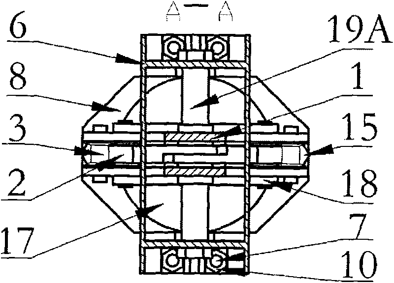
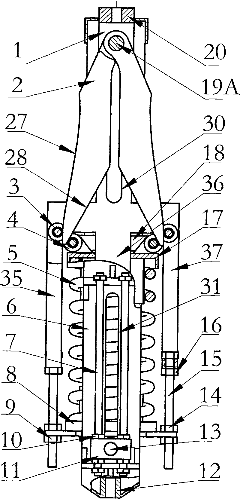
[0044] Such as figure 1 , figure 2 and image 3 As shown, this embodiment is mainly composed of a static frame 1, a cam 2, a static roller 3, a moving roller 4, a spring 5, a moving frame 6, a locking screw 7, a lower spring end cover 8, an adjusting nut 9, a locking nut 10, and a locking block. 11. Connecting nut 12, indicating pin 13, locking nut 14, adjusting bolt 15, locking nut 16, upper spring end cover 17, roller connecting rod 18, camshaft 19A, connecting nut 20, etc.

[0045] The moving frame 6 is mainly welded by two rectangular plates, and its overall structure and composition are symmetrical. The static frame 1 is located in the middle of the two symmetrical plates of the moving frame 6. The moving frame 6 has multiple functions: a camshaft is used on the top 19A is hinged with two cams 2, and the cam is formed with an inner working curve 28 and an outer working curve 27. The above two working curves cooperate with the moving roller 4 and the static roller 3 res...

Embodiment 2

[0052] Such as Figure 4 As shown, the overall structure, composition and working principle of the present embodiment are basically the same as those of the first embodiment, and the supporting method is also the same as that of the first embodiment: the static frame 1 is hung on the external support structure through the suspender 39 and the locking nut 38 , the moving frame 6 is connected to the pipeline and equipment through the suspension rod 23 and the lock nut 24 . There are mainly two differences: first, the two cams 2 of this embodiment are not coaxial, and are hinged on both sides of the moving frame 6 with a camshaft 19B respectively. Another guide shaft 21 is installed between 19B; the second, the outer working curve 27 of the cam is a straight line reference curve, and the inner curve 28 is a calculation curve.

Embodiment 3

[0054] Such as Figure 5As shown, the overall structure, composition, supporting mode and working principle of the present embodiment are basically the same as those of the second embodiment, and there are two main differences: first, the two camshafts 19B of this embodiment are placed between the moving roller 4 and the static roller. Below the gap of the roller 3, when the camshaft 19 moves downward, the cam 2 is "drawn out" from the gap between the driven and static rollers 4 and 3, rather than "inserted". This design can reduce the longitudinal dimension; Two, the outer working curve 27 of the cam 2 is a curve, while the inner curve 28 is a straight line reference curve.


PUM


Abstract

The invention relates to a self-compensating constant-force spring hanger, which mainly comprises a static frame, a dynamic frame, a cam, a spring, upper and lower spring end covers and static and dynamic idler wheels. The cam hinged on the dynamic frame by a cam shaft is provided with two inner and outer working curves which ensure a supporting and hanging force constant and are matched with the dynamic and static idler wheels arranged on the upper spring end cover and the static frame respectively. The spring and the upper and lower spring end covers are sleeved on a middle arm of the static frame. The lower spring end cover is connected with the static frame by an adjusting nut and an adjusting screw. The dynamic frame is provided with a locking support plate which can lock an indicating pin fixedly connected on the static frame after being matched with a locking device. The self-compensating constant-force spring hanger can be used for supporting and hanging pipelines with cold and thermal displacement in the industries, such as the power industry, the petrochemical industry and the like, and also can be used in the occasions that contact lines and the like of electrified railways needs the constant tensile force.

Description

technical field [0001] The invention relates to a support and hanger, in particular to a constant force spring support and hanger. Background technique [0002] At present, in order to reduce the additional stress caused by thermal expansion and contraction of pipelines, two kinds of constant force spring supports and hangers are widely used in electric power, petrochemical and other industries: connecting rod type and main and auxiliary type. [0003] The application number is 87207385, and the Chinese patent entitled "Constant Force Spring Hanger" shows a connecting rod type constant force spring hanger. The spring support and hanger is based on the principle of moment balance, and the main components are the rotary frame, the fixed frame, and the spring. Wherein, the fixed frame is hinged with the revolving frame by a shaft, and the revolving frame is connected with the spring through the pull plate and the pull rod bolt. When a fixed external load makes the revolving f...

Claims


Application Information

Patent Timeline
Patent Type & Authority Applications(China)
IPC IPC(8): F16L3/21
Inventor 高永峰张相炎
Owner 高永峰
Why Eureka
Try Eureka