Thermoacoustically-driven thermally-coupled two-stage pulse tube cooling system

A pulse-tube refrigeration and pulse-tube refrigerator technology, applied in refrigerators, refrigeration and liquefaction, gas cycle refrigerators, etc., can solve problems such as damage and structural distortion, achieve improved pressure ratio, good low-temperature refrigeration performance, and ensure long-term The effect of stable operation

Inactive Publication Date: 2010-05-12
ZHEJIANG UNIV
View PDF0 Cites 32 Cited by
  • Summary
  • Abstract
  • Description
  • Claims
  • Application Information

AI Technical Summary

Problems solved by technology

In addition, the problem of thermal expansion in the loop structure also needs to be carefully

Method used


Image

  • Thermoacoustically-driven thermally-coupled two-stage pulse tube cooling system
  • Thermoacoustically-driven thermally-coupled two-stage pulse tube cooling system
  • Thermoacoustically-driven thermally-coupled two-stage pulse tube cooling system

Examples


Embodiment Construction

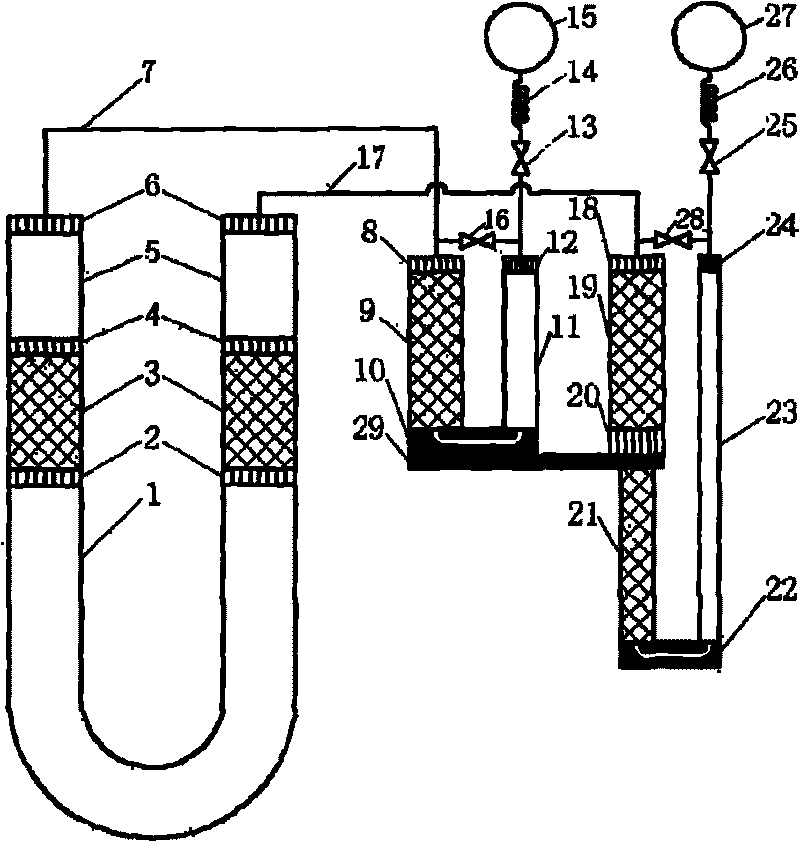
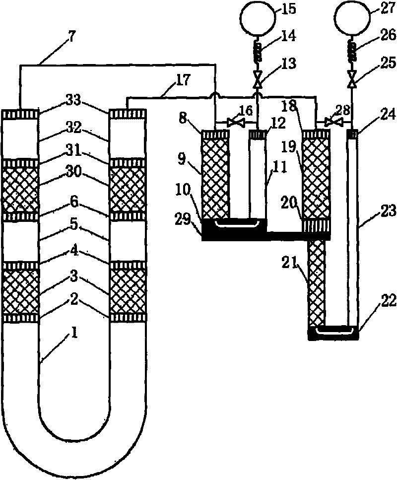
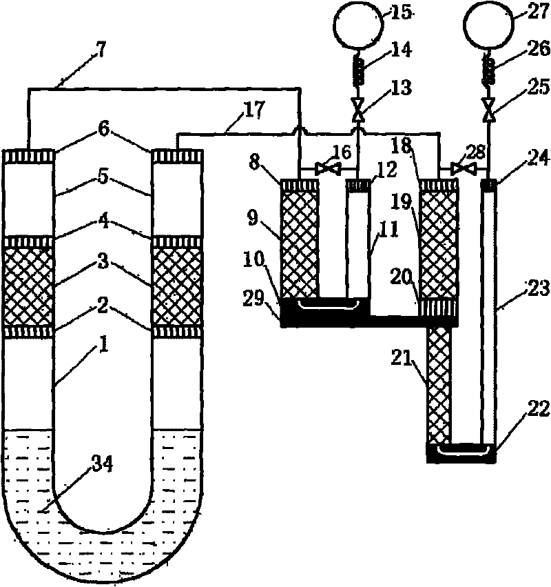
[0017] The invention proposes a novel thermoacoustic-driven heat-coupled two-stage pulse tube refrigeration system aimed at the low-temperature temperature region. In this system, the thermoacoustic engine uses a U-shaped resonant tube to connect two linearly arranged thermoacoustic cores, and the pulse tube refrigerator is a thermally coupled two-stage pulse tube refrigerator with independent gas paths. The core drives the first and second stages of the pulse tube refrigerator, respectively. The two stages of the pulse tube refrigerator are respectively connected at the pressure antinode positions at both ends of the thermoacoustic engine to utilize the maximum pressure ratio of the thermoacoustic engine. At the same time, the non-loop structure avoids the influence of Gedeon DC on the efficiency and the possible thermal expansion. Related structural damage problems. At the same time, in this system, the sound work generated by the thermoacoustic plate stack flows out from i...


PUM


Abstract

The invention discloses a thermoacoustically-driven thermally-coupled two-stage pulse tube cooling system, which comprises a U-shaped double side-drive thermoacoustic engine, connecting pipes and a thermally-coupled two-stage pulse tube cooler, which are connected sequentially. The system is characterized in that: a U-shaped resonating tube connects two thermoacoustic cores; acoustic power flows flow out from the directions of a cold end and a hot end of a thermoacoustic plate stack to drive an acoustic oscillator and the pulse tube cooler in the U-shaped resonating tube respectively; the backward pressure waves output by the two thermoacoustic cores drive the two stages of the thermally-coupled two-stage pulse tube cooler through the connecting pipes respectively, the pulse tube cooler is connected to the pressureantinode positions on the two ends of the thermoacoustic engine, and a larger output pressure ratio is favorable for the acquisition of optimal lower cooling performance of the pulse tube cooler; the operation method of combining the thermoacoustic plate stack and a thermoacoustic regenerator is adopted to improve the acoustic power output capacity and the vehicle efficiency; and a liquid piston is introduced into the U-shaped resonating tube to form a gas-liquid coupled oscillation system so as to reduce resonance frequency and increase pressure ratio and consequentially improve the performance of the driven pulse tube cooler.

Description

technical field [0001] The invention relates to a heat-driven refrigeration device, in particular to a low-temperature refrigeration device driven by a thermoacoustic engine. Background technique [0002] The thermoacoustic-driven pulse tube refrigeration system is a heat-driven refrigeration system that uses a thermoacoustic engine (also called a thermoacoustic compressor) to drive a pulse tube refrigerator to obtain a cooling effect. The thermoacoustic engine generates self-excited oscillation of the working medium under the drive of heat energy, that is, converts heat energy into sound work, and outputs it in the form of pressure waves; the pulse tube refrigerator consumes the sound work transmitted by pressure waves to achieve heat pumping and obtain cooling effect. Since the thermoacoustic driven pulse tube refrigeration system is only composed of heat exchangers and pipes, and does not include mechanical moving parts such as cranks, connecting rods, and pistons, it has...

Claims


Application Information

Patent Timeline
IPC IPC(8): F25B9/14
CPCF25B2309/1403F25B2309/1408F25B2309/14241F25B9/145F25B9/10
Inventor 汤珂雷田金滔林小钢张玙
Owner ZHEJIANG UNIV
Why Eureka
Try Eureka