Semiconductor device
A semiconductor and depletion layer technology, applied in the structure and manufacturing process of junction barrier Schottky devices, can solve the problems affecting device application, low forward voltage drop switching speed, low reverse voltage, etc., and achieve electrical parameters Characteristic optimization, the effect of reducing reverse leakage current and reducing forward voltage drop
- Summary
- Abstract
- Description
- Claims
- Application Information
AI Technical Summary
Problems solved by technology
Method used
Image
Examples
Embodiment 1
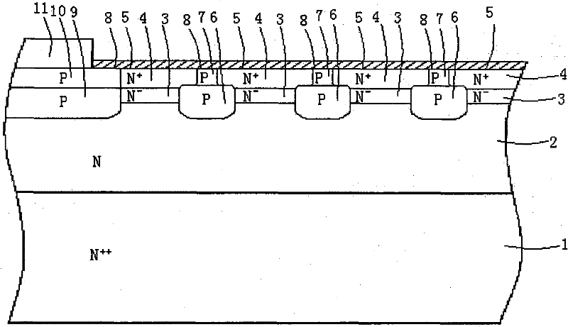
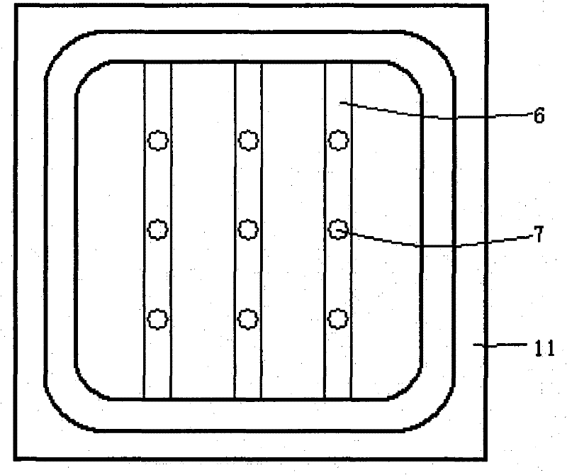
[0039] as attached figure 1 , attached figure 2 Shown is a schematic cross-sectional view and a top view of the first embodiment of the present invention.
[0040] The semiconductor device of the present invention includes: N-type substrate region 1, which is an N-type conductivity type semiconductor substrate material, and the cathode is drawn out through a metal on the lower surface of the substrate layer; N-type drift layer 2, which is an N-type conductivity type semiconductor material, is located On the N-type substrate region 1; the N-type depletion layer 3 is a semiconductor material of the N-type conductivity type, located on the N-type drift layer 2; the N-type heavily doped layer 4 is a semiconductor material of the N-type conductivity type, Located on the N-type depletion layer 3; the semiconductor material and metal on the top of the N-type heavily doped layer 4 form a Schottky barrier layer 5, and a layer of conductive metal is covered on the Schottky barrier lay...
Embodiment 2
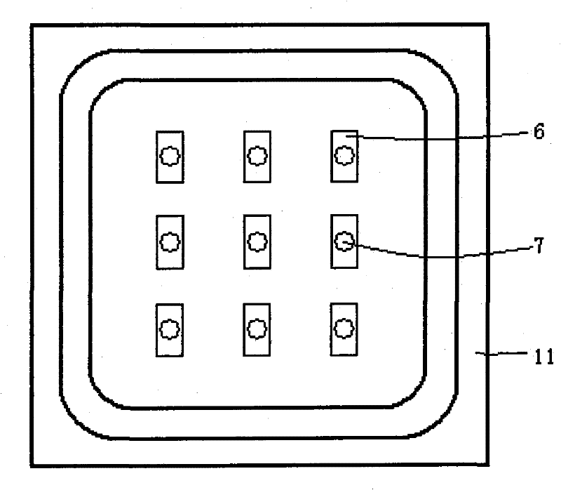
[0046] as attached image 3 As shown, nine strip-shaped reverse-bias leakage current suppression P-type regions 6 are separately formed in the N-type drift layer 2 and the N-type depletion layer 3, and the width of each reverse-bias leakage current suppression P-type region 6 is set to The distance between two adjacent P-type regions 6 for suppressing reverse bias leakage current is 2-6um; nine small-area P-type regions 7 separated from each other are formed in the N-type heavily doped layer 4, each Two small-area P-type regions 7 are connected to corresponding reverse-bias leakage current suppressing P-type regions 6, the distance between two adjacent small-area P-type regions 7 is 2-20um, and the diameter of each small-area P-type region 7 circle is 1~5um; the phosphorus impurity concentration in the drift layer is 1×10 16 atom / cm 3 , the phosphorus impurity concentration in the depletion layer is chosen to be 1×10 15 atom / cm 3 , the concentration of phosphorus atoms dop...
Embodiment 3
[0048] The structure and manufacturing process are as in Example 1, and the phosphorus impurity concentration in the drift layer is selected as 5×10 16 atom / cm 3 , the phosphorus impurity concentration in the depletion layer is chosen to be 5×10 15 atom / cm 3 , the concentration of doped phosphorus atoms in the substrate layer is selected as 1×10 20 atom / cm 3 , the phosphorus impurity concentration in the heavily doped layer is chosen to be 8×10 16 atom / cm 3 .
PUM
 Abstract
Description
Claims
Application Information
 - R&D
- Intellectual Property
- Life Sciences
- Materials
- Tech Scout
- Unparalleled Data Quality
- Higher Quality Content
- 60% Fewer Hallucinations
Browse by: Latest US Patents, China's latest patents, Technical Efficacy Thesaurus, Application Domain, Technology Topic, Popular Technical Reports.
© 2025 PatSnap. All rights reserved.Legal|Privacy policy|Modern Slavery Act Transparency Statement|Sitemap|About US| Contact US: help@patsnap.com


