LED constant current driving circuit

A technology of constant current drive and circuit, applied in the direction of circuit layout, lamp circuit layout, electric light source, etc., can solve the problem of unsatisfactory constant current effect of constant current circuit, and achieve simple and adjustable constant current value, simple circuit and high precision Effect

Inactive Publication Date: 2010-05-12
OCEANS KING LIGHTING SCI&TECH CO LTD +1
View PDF0 Cites 20 Cited by
  • Summary
  • Abstract
  • Description
  • Claims
  • Application Information

AI Technical Summary

Problems solved by technology

[0005] The technical problem to be solved by the present invention is to provide a constant current with high precision, adjustable constant current value, high reliability, simple circuit and low cost for the defects of the above-mentioned constant current circuit in the prior art. Low LED constant current drive circuit

Method used


Image

  • LED constant current driving circuit
  • LED constant current driving circuit
  • LED constant current driving circuit

Examples


Embodiment Construction

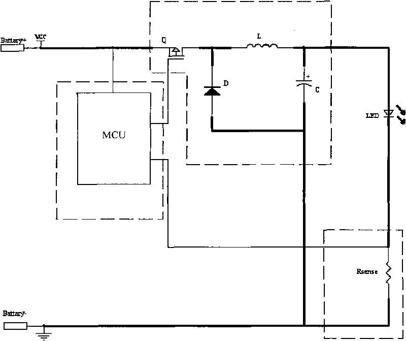
[0023] The invention utilizes the constant current chip to sample the output electric signal of the load to the MCU, and then controls the constant current chip through the MCU to perform constant current precise control and circuit protection.

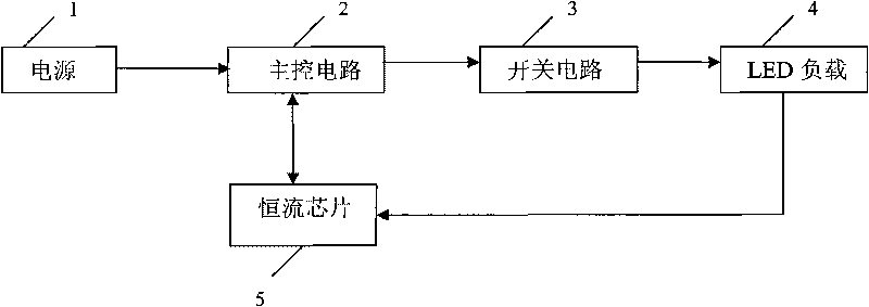
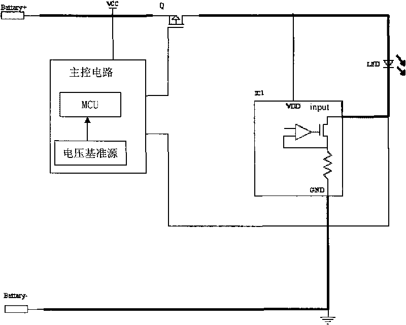
[0024] see figure 2 , which shows the principle block diagram of the present invention. The LED constant current drive circuit provided by the present invention includes: power supply 1, main control circuit 2, switch circuit 3, LED load 4, and constant current chip 5. Constant current chip 5 and LED The load 4 is connected in series, and the input terminal of the constant current chip 5 is connected to the cathode of the LED load 4. The main control circuit 2 is connected to the power supply 1, and the main control circuit 2 includes an MCU and a voltage for providing a reference voltage to the MCU connected to the MCU. The reference source, the signal sampling terminal of the MCU is connected to the cathode of the LED load, so as t...


PUM


Abstract

The invention relates to an LED constant current driving circuit comprising LED load, a power supply, and also at least one constant current chip, a main control circuit and a switching circuit, wherein the at least one constant current chip is electrically connected with the LED load and used for conducting constant current regulation on the LED load, the main control circuit is connected with the power supply and used for conducting pulse width modulation according to input signals of the constant current chip and outputting control signals, and the switching circuit is electrically connected between the control signal outputting end of the main control circuit and the LED load. The LED constant current driving circuit has the advantages of capability of supplying adjustable constant current value, high constant current accuracy, high efficiency, high circuit reliability, simple circuit and low cost.

Description

technical field [0001] The present invention relates to a driving circuit, more specifically, to an LED constant current driving circuit. Background technique [0002] Today, as a new generation of light sources, LEDs are used in a wider range of applications. However, LEDs generally require a constant driving current, and a slight instability of the current at both ends of the LED will cause flickering of the light emitted by the LED. At present, the low-voltage isolation-free high-power LED constant current drive circuit generally adopts the following two methods: [0003] 1. Use a buck circuit (buck) or a boost circuit (boost) or a pulse width modulation control (PWM, Pulse Width Modulator) LED constant current drive circuit combining buck and boost. In this way, the electrical signal output by the LED load is fed back to the main control unit (MCU, Micro Controller Unit), and then the internal program algorithm of the MCU is used for PWM modulation to achieve the effec...

Claims


Application Information

Patent Timeline
Patent Type & Authority Applications(China)
IPC IPC(8): H05B37/02F21V23/00F21Y101/02F21Y115/10
Inventor 周明杰张玉平
Owner OCEANS KING LIGHTING SCI&TECH CO LTD
Why Eureka
Try Eureka