Braking force regulator based on wire control braking system

A technology of brake-by-wire and braking force, applied in the direction of brake, brake transmission, transportation and packaging, etc., can solve the problems of many influencing factors, unstable braking, complex actuator, etc., to improve the reaction speed, reduce the body The effect of weight

Inactive Publication Date: 2010-05-19
CHERY AUTOMOBILE CO LTD
View PDF6 Cites 7 Cited by
  • Summary
  • Abstract
  • Description
  • Claims
  • Application Information

AI Technical Summary

Problems solved by technology

The control of the braking force can be realized through these two technologies, but their disadvantage is that the actuator is relatively complicated, and the traditional hy

Method used


Image

  • Braking force regulator based on wire control braking system
  • Braking force regulator based on wire control braking system

Examples


Embodiment Construction

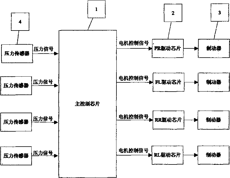
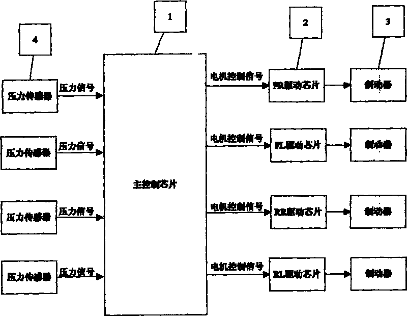
[0014] Such as figure 1 As shown, the regulator is mainly composed of a main control chip 1, a pressure sensor 4, a drive unit 2 and an electric brake 3. The main control chip 1 adopts the MPC5604P chip provided by FREESCALE, the pressure sensor 4 adopts Yongzheng load cell 266AH, the drive unit 2 adopts the BTN7960P chip of INFENION, and the electric brake 3 is a brake caliper with a built-in motor. Wherein, the pressure sensor 4 is installed on the friction plate, is connected with the main control chip 1 through the wiring harness, and transmits the pressure signal to the main control chip 1; Connect to receive the motor control signal sent by the main control chip 1; the electric brake 3 is installed on the original position of the brake caliper on the car, and the actuator integrated with the brake caliper replaces the original hydraulic brake caliper and is installed on the brake disc superior.

[0015] Utilizing the automobile braking force regulator of the present in...


PUM


Abstract

The invention discloses a braking force regulator based on a wire control braking system, comprising a main control chip (1), a pressure sensor (4), a drive unit (2) and an electric brake (3). The braking force regulator is characterized in that the pressure sensor (4) is installed on a friction plate and is connected with the main control chip (1) via a wire harness to send a pressure signal to the main control chip (1); the drive unit (2) is connected with the main control chip (1) to receive a motor control signal sent by the main control chip (1); and the electric brake (3) is installed on the position on which a brake calliper is planed to be installed. The invention can directly control the output torque of a DC motor on an automobile so as to directly control braking force applied on a brake disk. Because of totally adopting electric signals, the traditional hydraulic machinery structure is cancelled, so that automobile body weight is lightened, and braking reaction speed is improved.

Description

technical field [0001] The invention relates to the braking force control of the wire-controlled braking system, in particular to a braking force regulator based on the wire-controlled braking system. Background technique [0002] Currently, the known technologies include: vehicle braking force control device and its control method (CN03102116.6), vehicle braking force control (CN200510074777.3), the former includes: a brake operating part 16, and a control part 50, At the moment when a first predetermined time (ΔT1) has elapsed since the driver's operation state of the brake operation member 16 becomes a predetermined operation state, when the driver's operation amount of the brake operation member 16 is equal to or greater than the operation When the amount is a reference value, the above-mentioned control section activates a brake assist control to generate a braking force higher than usual. The latter includes a controller for controlling the actual braking force of the...

Claims


Application Information

Patent Timeline
IPC IPC(8): B60T8/17B60T13/74
Inventor 杜金枝
Owner CHERY AUTOMOBILE CO LTD
Why Eureka
Try Eureka