Supercharge Your Innovation With Domain-Expert AI Agents!

Inductance and resistance compensating type capacitive voltage divider

A capacitor voltage divider and resistance compensation technology, applied in the field of resistance compensation capacitor voltage divider and inductance, can solve waveform distortion, resistance-capacitor parallel voltage divider is difficult to meet the condition of constant voltage divider ratio, voltage divider high frequency Problems such as poor response

Inactive Publication Date: 2010-05-19
XI AN JIAOTONG UNIV
View PDF0 Cites 12 Cited by
  • Summary
  • Abstract
  • Description
  • Claims
  • Application Information

AI Technical Summary

Problems solved by technology

Although the resistance-capacitance parallel voltage divider can also be used for the measurement of pulse voltage, it is difficult for the commonly used resistance-capacitance parallel voltage divider to meet the condition of constant voltage division ratio, and there is also the problem of waveform distortion during measurement.
[0003] Using the resistive compensation method of resistance-capacitance series voltage division, the damping resistance cannot be too large. Excessive damping resistance will make the high-frequency response of the voltage divider worse, but a small damping resistance may cause the voltage divider to generate a large The wave head oscillates, and the problem of frequency bandwidth has not been well resolved

Method used


Image

  • Inductance and resistance compensating type capacitive voltage divider
  • Inductance and resistance compensating type capacitive voltage divider
  • Inductance and resistance compensating type capacitive voltage divider

Examples


Embodiment Construction

[0013] The present invention will be described in further detail below in conjunction with the accompanying drawings.

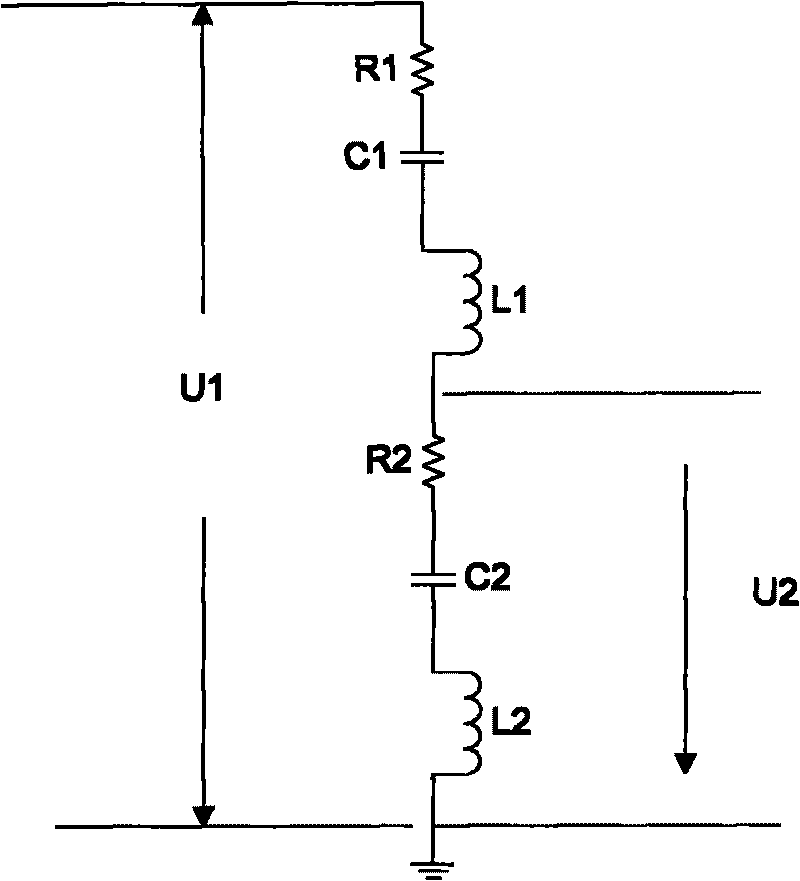
[0014] see figure 1 , due to the energy consumption of dielectric polarization, ohmic resistance of electrodes, partial discharge, etc., the high-frequency equivalent model of the low-voltage arm adopts the resistance R 2 , inductance L 2 and capacitance C 2 series circuits, such as figure 1 shown. figure 1 Medium, C 1 is the capacitance of the high voltage arm, L 1 , R 1 are the compensation inductance and compensation resistance of the high-voltage arm, respectively. The present invention includes a high-voltage arm and a low-voltage arm connected by a coaxial connector, and the capacitor C on the high-voltage arm 1 The compensation inductance L used to compensate the parasitic parameter effect of the low-voltage arm is added on both sides of the 1 and compensation resistor R 1 , according to the physical structure and frequency domain response ch...


PUM


Abstract

The invention designs an inductance and resistance compensating type capacitive voltage divider which is used for the measurement of nanosecond grade transient high voltage of a power pulse or power system. The voltage divider comprises a high-voltage arm and a low-voltage arm, wherein the high-voltage arm is connected with the low-voltage arm by a coaxial connecting head; a compensating inductance and a compensating resistance which are used for compensating the parasitic parameter effect of the low-voltage arm are additionally arranged on the high-voltage arm; and the low-voltage arm adopts a voltage dividing box comprising discrete components and is formed by coaxially connecting a plurality of capacitors in parallel to be placed into a metal shielding box. The invention can convert a high amplitude transient voltage signal into a low-voltage signal which can be measured by recording instruments, such as an oscilloscope, and the like in a lossless way.

Description

technical field [0001] The invention relates to a capacitive voltage divider, in particular to an inductance and resistance compensation type capacitive voltage divider used in pulse power or power systems for nanosecond-level high-voltage pulse measurement. Background technique [0002] At present, the voltage divider used to measure the impact high voltage mainly has two structures: capacitive and resistance-capacitance. Although the pure capacitive voltage divider only has an amplitude error, the capacitive voltage divider itself has an inductance. When measuring the impulse voltage , the wave head will inevitably produce high-frequency oscillations. Although the resistance-capacitance parallel voltage divider can also be used for the measurement of pulse voltage, it is difficult for the commonly used resistance-capacitance parallel voltage divider to satisfy the condition of constant voltage division ratio, and there is also the problem of waveform distortion during meas...

Claims


Application Information

Patent Timeline
IPC IPC(8): G01R15/06
Inventor 翟小社王建华耿英三王妍王振兴刘志远张国钢
Owner XI AN JIAOTONG UNIV
Features
  • R&D
  • Intellectual Property
  • Life Sciences
  • Materials
  • Tech Scout
  • Unparalleled Data Quality
  • Higher Quality Content
  • 60% Fewer Hallucinations
Learn More