
Lens eccentricity fine adjustment mechanism in projection lithography objective

A fine-tuning mechanism and projection light technology, which is applied in microlithography exposure equipment, optics, optical components, etc., can solve problems such as deviation tolerances, achieve the effects of preventing stress deformation and plane torsion, low cost, and improving imaging quality

Inactive Publication Date: 2010-05-19
INST OF OPTICS & ELECTRONICS - CHINESE ACAD OF SCI
View PDF0 Cites 1 Cited by
  • Summary
  • Abstract
  • Description
  • Claims
  • Application Information

AI Technical Summary

Problems solved by technology

[0003] The problem solved by the technology of the present invention is: in order to overcome the adverse effect on the image quality due to the slight eccentric change of the lens, a lens eccentric fine-tuning mechanism in the projection lithography objective lens is provided, so that the objective lens will not be affected by external forces during the position adjustment process. Stress deformation and torsion in the horizontal direction are produced by the action of the lens, making it possible to adjust the image quality on site, ensuring the tolerance of the center deviation of the lens, improving the adjustment accuracy of each lens to the axis, and overcoming the problem of image quality due to lens eccentricity. adverse effects on image quality, ensure the stability of image quality and focal plane, and ensure the quality of photolithography

Method used


Image

  • Lens eccentricity fine adjustment mechanism in projection lithography objective
  • Lens eccentricity fine adjustment mechanism in projection lithography objective
  • Lens eccentricity fine adjustment mechanism in projection lithography objective

Examples


Embodiment Construction

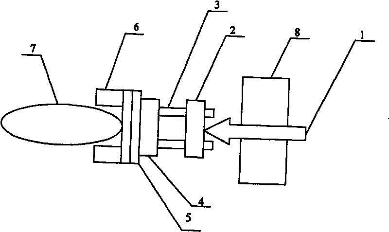
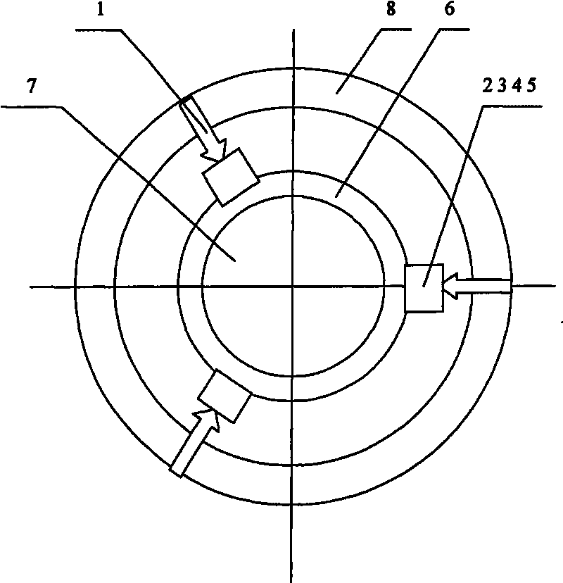
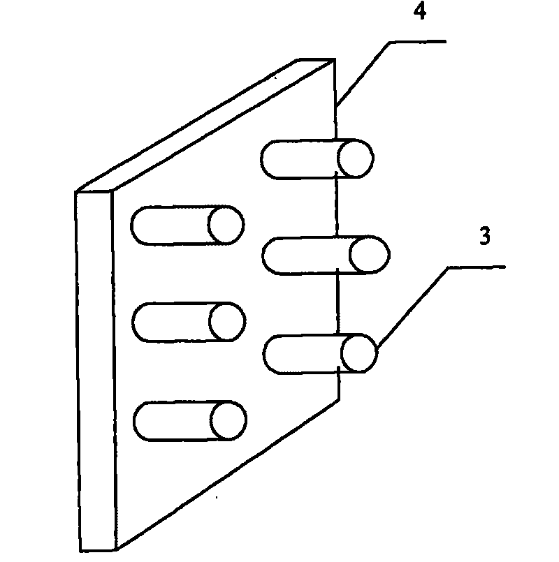
[0011] Such as figure 1 , 5 As shown, the lens eccentric fine-tuning mechanism of the present invention is installed on the lens frame 6 and the lens barrel 8, the lens frame 6 is located in the lens barrel 8, and there is a certain gap between the lens barrel 8 to ensure the displacement adjustment of the lens. The lens eccentric fine-tuning mechanism includes a fine-tuning head 1, a slider 2, a guide column 3, a guide column base 4, and an elastic pad 5. In the embodiment of the present invention, the elastic pad may be an elastic material such as elastic silicone. The fine tuning head 1 is installed in the lens barrel 8 and is perpendicular to the optical axis of the objective lens. The elastic pad 5 is installed on the side of the lens frame 6 . The contact surface between the guide post base 4 and the lens frame 6 is the elastic pad 5 . Such as image 3 , 4 As shown, the slider 2 is embedded in the guide column 3 on the guide column base 4. In order to ensure the line...


PUM


Abstract

The invention discloses a lens eccentricity fine adjustment mechanism in a projection lithography objective. The lens eccentricity fine adjustment mechanism is arranged on a lens frame and a lens barrel. The lens frame is positioned in the lens barrel and a certain gap is reserved between the lens frame and the lens barrel to guarantee a displacement adjustment quantity of a lens. The lens eccentricity fine adjustment mechanism comprises a fine adjustment head, a sliding block, a guide post, a guide post pedestal and an elastic cushion, wherein the fine adjustment head is arranged in the lens barrel and is vertical to an optical axis of the objective; an elastic guide mechanism is arranged on a lateral surface of the lens frame, and a contact surface of the guide post pedestal and the lens frame is the elastic guide mechanism; and the sliding block is embedded in the guide post on the guide post pedestal. The lens eccentricity fine adjustment mechanism can perform accurate eccentricity adjustment on each lens in the projection lithography objective to meet the requirement of an offset tolerance of the center of the lens, the alignment accuracy of each lens for the axle centre is improved, adverse effects on the image quality caused by lens eccentricity are overcome, the stability of the image quality and the focal plane is guaranteed, and the lithography quality is guaranteed.

Description

technical field [0001] The invention relates to a lens eccentric fine-tuning mechanism in a projection lithography objective lens. technical background [0002] Since the projection lithography objective lens is composed of multiple lenses, its image quality is close to the diffraction limit, so slight eccentric changes of the lenses will have a negative impact on the image quality, which makes the micro-adjustable function of the on-site image quality very necessary. At present, none of the existing fine-tuning mechanisms can guarantee the stress and deformation requirements of the lens caused by the objective lens during the position adjustment process, and the torsion requirements in the horizontal direction. Contents of the invention [0003] The problem solved by the technology of the present invention is: in order to overcome the adverse effect on the image quality due to the slight eccentric change of the lens, a lens eccentric fine-tuning mechanism in the projectio...

Claims


Application Information

Patent Timeline
Patent Type & Authority Applications(China)
IPC IPC(8): G02B7/02G03F7/20
Inventor 王建胡松赵立新邢薇
Owner INST OF OPTICS & ELECTRONICS - CHINESE ACAD OF SCI
Learn More