Anchor drawplate type cable-beam anchorage structure for cable-stayed bridge

A cable beam anchoring and anchoring plate technology, applied in the field of bridge engineering, can solve the problems of reduced procurement and inspection costs, low fatigue strength, etc., and achieve the effects of reduced procurement and inspection costs, high fatigue strength, and reasonable structural form

Inactive Publication Date: 2010-05-26
GUANGDONG PROVINCE COMM PLANNING & DESIGN INST
View PDF0 Cites 8 Cited by
  • Summary
  • Abstract
  • Description
  • Claims
  • Application Information

AI Technical Summary

Problems solved by technology

[0007] The present invention connects the extension section of the longitudinal web of the steel main girder with the anchor stay plate, compared with the existing method in which the bottom of the anchor stay plate is directly welded to the top plate of the steel girder, avoiding the cross welding stress in the main force direction Concentrated phenomenon, and at the same time solve the problem

Method used


Image

  • Anchor drawplate type cable-beam anchorage structure for cable-stayed bridge
  • Anchor drawplate type cable-beam anchorage structure for cable-stayed bridge
  • Anchor drawplate type cable-beam anchorage structure for cable-stayed bridge

Examples


Embodiment Construction

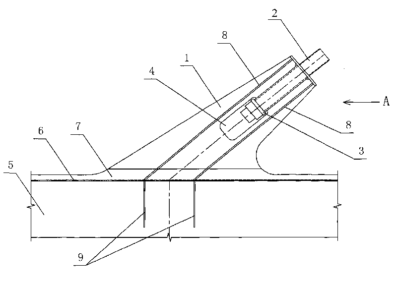
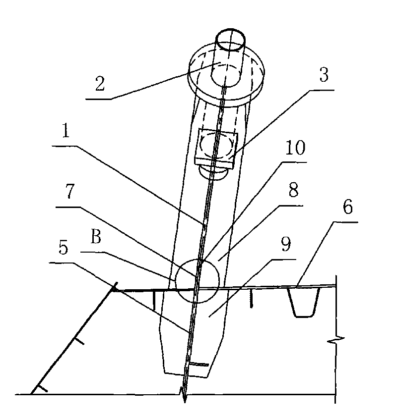
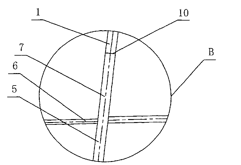
[0027] Such as Figure 1~3 Shown, is the present invention a kind of cable-stayed bridge anchor pull plate type cable girder anchorage structure, comprises steel girder and the anchor pull plate assembly that is arranged on the top surface of steel girder, anchor pull plate assembly comprises anchor pull plate 1, is used for The anchor pipe 2 with the stay cable and the anchor backing plate 3 arranged at the bottom of the anchor pipe 2 and installed vertically with the anchor pipe 2, the anchor stay plate 1 is selected according to the size of the cable force of the stay cable, and the anchor stay plate 1 is There is a counterbore-shaped groove 4 in the center of the top along the central axis. The size of the notch of the groove 4 should meet the space requirements for the hanging operation of the stay cable. The anchor pipe 2 is installed in the upper part of the groove 4. The outer wall of the pipe 2 and the inner wall of the groove 4 are connected by penetration welding, t...


PUM


Abstract

The invention discloses an anchor drawplate type cable-beam anchorage structure for a cable-stayed bridge, which comprises a main steel beam and an anchor drawplate component, wherein the anchor drawplate component is arranged on the top surface of the main steel beam; the anchor drawplate component comprises an anchor drawplate, an anchor pipe and an anchor backing plate, wherein the anchor pipe is used for penetrating a stayed-cable; the anchor backing plate is arranged at the bottom of the anchor pipe and installed vertically to the anchor pipe; a counter bore-shaped groove is arranged in the top center position of the anchor drawplate along a central axis direction; the anchor pipe is installed at the upper part of the groove; a through hole corresponding to a pipe orifice of the anchor pipe is arranged on the anchor backing plate; a stayed-cable anchor head connected with a stayed-cable end head is installed at the lower part of the groove; a longitudinal web plate of the main steel beam extends upwards; an extending section on the longitudinal web plate corresponding to the bottom edge of the anchor drawplate protrudes out of a top plate of the main steel beam to form an outer web plate; and the bottom edge of the anchor drawplate is connected with the edge of the upper end of the outer web plate. The invention uses a connection structure of the outer web plate and the anchor drawplate and solves the problem of low fatigue strength of a cross welding structure; the top plate of the main steel beam is not required to have a Z-direction tear resisting characteristic, thus the material purchase and inspection charges are notably reduced and the structure stress is safer and more reliable.

Description

technical field [0001] The invention relates to the technical field of bridge engineering, in particular to a cable-beam anchoring structure. Background technique [0002] In the technical field of cable-stayed bridge engineering, the anchored connection between the cable-stayed cables and the steel girder is a key factor in the design. Since the anchored connection structure is under huge load for a long time, the reliability of its mechanical performance is directly related to the overall Therefore, it is one of the first conditions to ensure the safety of the bridge to develop a reasonable cable-beam anchorage structure. [0003] In the existing steel box girder cable-stayed bridge, the anchorage forms of the cable-stayed cable and the steel girder mainly include loose cable saddle plus anchor beam type, corbel (bracket) type, anchor tube type, anchor box type, and anchor-stayed plate type. , ear plate type, etc. Among them, the cable-stayed bridge anchor-plate type cab...

Claims


Application Information

Patent Timeline
IPC IPC(8): E01D19/00E01D19/14E01D11/04
Inventor 梁立农代希华孙向东李江山王强梁倬贤
Owner GUANGDONG PROVINCE COMM PLANNING & DESIGN INST
Why Eureka
Try Eureka