Method for prolonging service life of infrared touch screen

An infrared touch screen, working life technology, applied in the input/output process of data processing, instruments, electrical digital data processing, etc., can solve the design and production cost of infrared touch screen, the limited contribution of infrared touch screen working life, can not prevent emission Tube aging problems and other problems, to achieve the effect of easy debugging, low production cost, and improved working life

Inactive Publication Date: 2011-10-05
深圳新山鹰互动技术有限公司
View PDF1 Cites 0 Cited by
  • Summary
  • Abstract
  • Description
  • Claims
  • Application Information

AI Technical Summary

Problems solved by technology

However, this technical solution also has disadvantages
First of all, this technical solution does not really propose a solution to the aging problem of the launch tube itself, but only proposes a solution for the aging of the launch tube, so it cannot prevent the aging problem of the launch tube, which is equivalent to an after-the-fact remedial plan, and in the remedy At the same time, the launch tube is still aging, so the contribution to extending the working life of the infrared touch screen is limited
Especially for the situation where most of the time such as touch TV is in the screen display state, and the proportion of the touch operation time is very small relative to the time when the entire device is turned on, it is still difficult to increase the working life of the infrared touch screen to the same level as other parts of the device. The degree of matching the working life of the infrared touch screen; secondly, the use of software and hardware structures such as A / D converters and normalization algorithms increases the complexity of the system, resulting in an increase in the design and production costs of infrared touch screens

Method used


Image

  • Method for prolonging service life of infrared touch screen
  • Method for prolonging service life of infrared touch screen
  • Method for prolonging service life of infrared touch screen

Examples


Embodiment Construction

[0016] The basic embodiments of the present invention will be described below in conjunction with the accompanying drawings. Because the technical solution involved in the present invention is about the scanning detection method, other specific structures of the infrared touch screen will not be given in the embodiments.

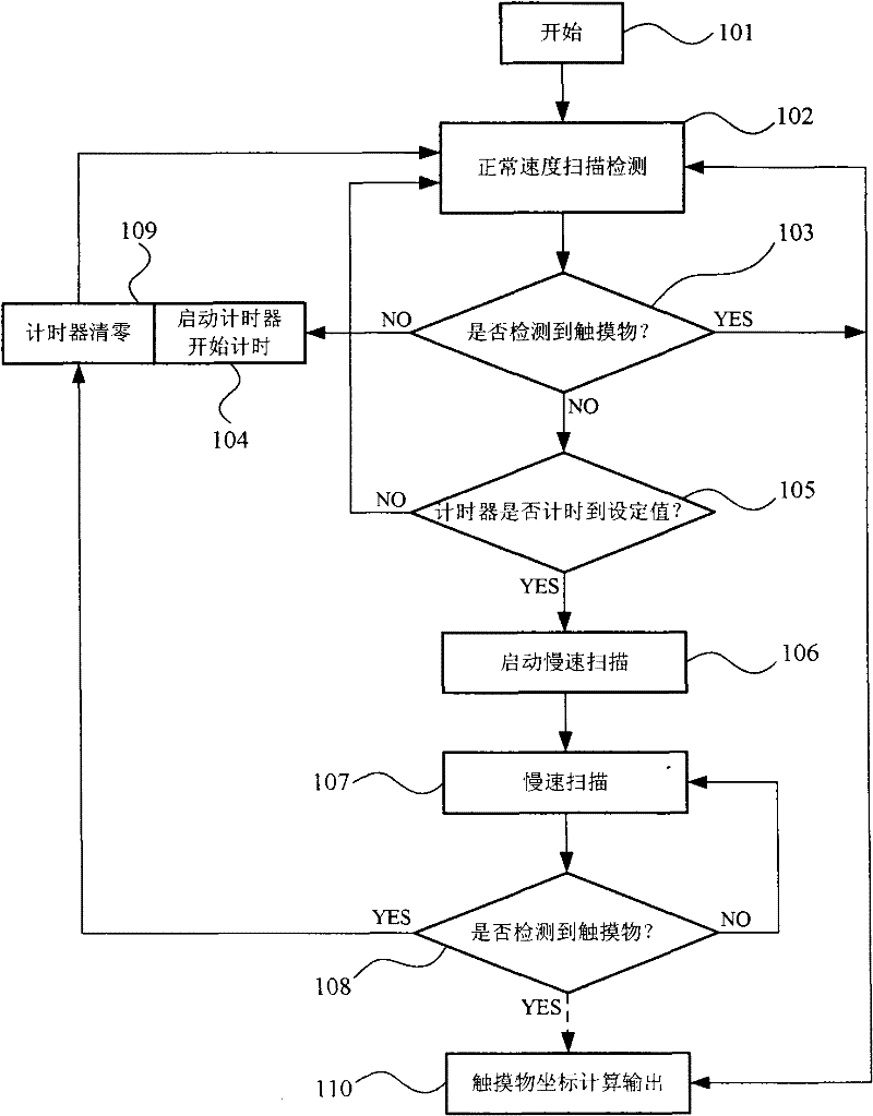
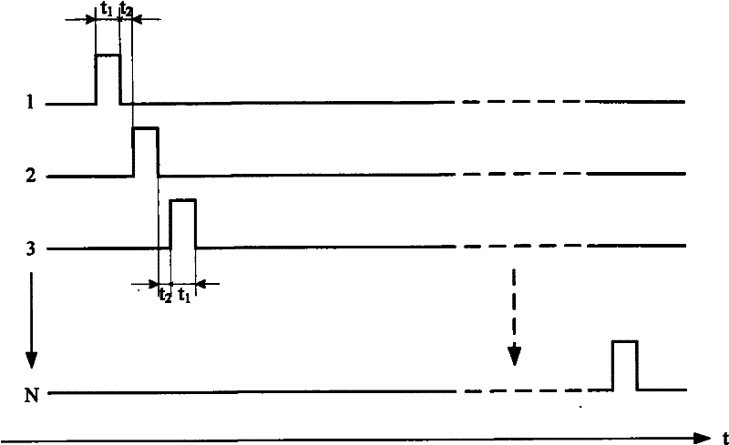
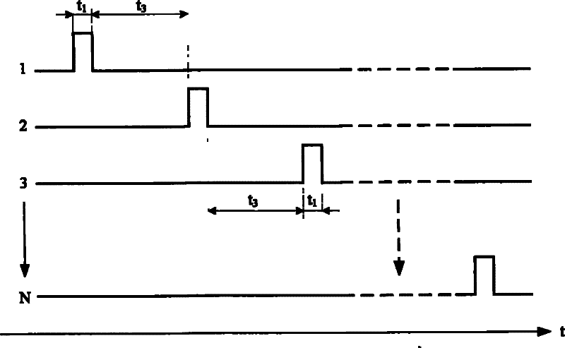
[0017] figure 1 The program flow chart shown is a code structure capable of realizing the object of the present invention, which is used in a microcontroller (MCU) inside the infrared touch screen. It can be seen from the figure that the principle of the present invention is to reduce the scanning speed of the touch screen when the touch screen is idle, and reduce the ratio of the conduction time and cut-off time of the infrared emitting tube within a unit time, thereby realizing the purpose of prolonging the service life of the touch screen. Let's pass the figure 1 A description of the structure shown is used to describe in detail a specific embodiment of...


PUM


Abstract

The invention relates to a method for prolonging the service life of an infrared touch screen. The method is applied to the infrared touch screen which comprises a plurality of pairs of one-to-one infrared emission pipes and receiving pipes arranged in a frame of an infrared touch device. In the method, a timer is used, so that when the touch screen is not operated for a period of time, a microcontroller controls the infrared emission pipes to convert into a low-speed scanning state from a normal-speed scanning state, and monitors whether a touching object exists; and when the touching objectis detected under the low-speed scanning state, the normal-speed scanning state is restored at once. Through the low-speed scanning state in the method, the time ratio of switching on the infrared emission pipes is greatly reduced in the period of time when the touch screen is not operated, and the service life of the touch screen is greatly prolonged under the condition that the aging trend and time of the emission pipes are not changed along the switch-on time; and at the same time, the hardware structure of the infrared touch screen is not changed basically, and the method has the advantages of low production cost, easy adjustment and the like.

Description

technical field [0001] The invention relates to a method for prolonging the working life of an infrared touch device, which belongs to the technical field of computer human-computer interaction, in particular to the technical field of touch point detection and scanning for an infrared touch device. Background technique [0002] The main structure and principle of the existing infrared touch screen is to install several pairs of infrared emitting and receiving tubes on the frame, and then use the microcontroller system inside the touch screen to control the drive module for driving the infrared emitting tube through the I / O port and a gating module for gating the infrared receiving tubes, sequentially driving and gating each pair of infrared emitting and receiving tubes in a certain order, and completing the scanning detection of the surface to be detected in the vertical and horizontal directions. In this process, by detecting whether the infrared rays between the emitting a...

Claims


Application Information

Patent Timeline
Patent Type & Authority Patents(China)
IPC IPC(8): G06F3/042
Inventor 肖衣鉴
Owner 深圳新山鹰互动技术有限公司
Why Eureka
Try Eureka