Antenna and reader/writer device

A reader/antenna technology, applied to antennas, resonant antennas, antenna components, etc., can solve problems such as increasing the size of the antenna and increasing the size of the conductor pattern

Active Publication Date: 2010-05-26
FUJITSU LTD
View PDF3 Cites 4 Cited by
  • Summary
  • Abstract
  • Description
  • Claims
  • Application Information

AI Technical Summary

Problems solved by technology

[0007] However, for this antenna, if an inexpensive substrate with a low dielectric constant such as an FR-4 substrate is used, it may be necessary to increase the length of the conductor pattern to ensure that the radiated power supplied to the IC tag is large enough, thus increasing the size of the conductor pattern. The size of the pattern in the length direction
The result increases the size of the overall antenna

Method used


Image

  • Antenna and reader/writer device
  • Antenna and reader/writer device
  • Antenna and reader/writer device

Examples


Embodiment Construction

[0025] Exemplary implementations of the antenna and the reader / writer device according to the present invention will be described in detail below with reference to the accompanying drawings.

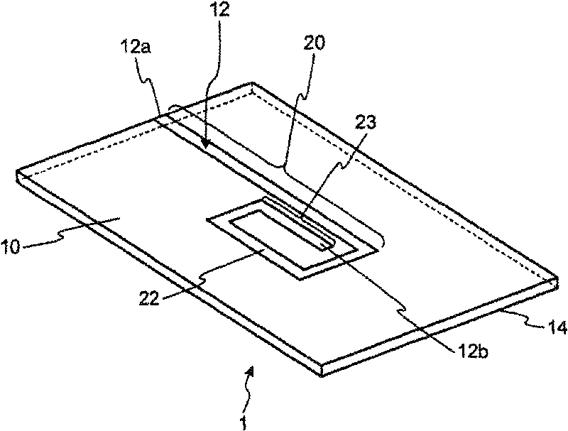
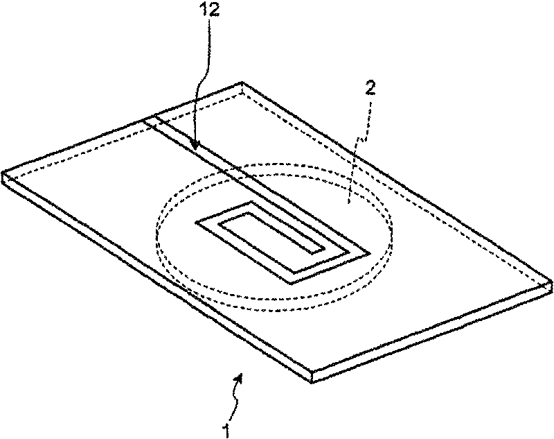
[0026] First, the configuration of an antenna according to one embodiment of the present invention will be described. figure 1 is a perspective view of the configuration of the antenna 1 according to this embodiment; and figure 2 A state where the IC tag 2 is placed on the antenna 1 is schematically shown.

[0027] Such as figure 1 As shown, the antenna 1 includes: a substrate 10 made of a dielectric material (eg, FR-4) such as glass epoxy; a conductor pattern 12 formed on the substrate 10; and a ground (GND) 14 formed on the back surface of the substrate 10 opposite to the conductive pattern 12 . The conductor pattern 12 includes a power supply point 12a located at one end of the conductor pattern 12 and a free end 12b located at the other end of the conductor pattern 12 .

[002...


PUM


Abstract

An antenna for a RFID writer / reader includes a substrate made of a dielectric substance, and a conductor pattern formed on the substrate and including a feeding point, an open end, an extension part extending from the feeding point, and a spiral part extending spirally from an opposite end of the extension part to the open end. The spiral part includes a part juxtaposed with the extension part. Adistance along length directions of the conductor pattern, from a zero point at which a current is zero in the part upon feeding power to the feeding point, to a point at which a line perpendicular to the part and passing through the zero point intersects the extension part, is set to a second distance at which an electric field strength generated as a combination of electric fields generated at these points upon the feeding of power enables communications with the wireless tag.

Description

technical field [0001] Embodiments described herein relate to antenna and reader / writer devices. Background technique [0002] Recently, radio frequency identification (RFID) has been widely used as a non-contact automatic identification technology. In radio frequency identification, non-contact data communication is carried out by radio waves between an integrated circuit (IC) tag including a semiconductor memory and a reader / writer device from which the IC Data is read from and written to the tag's semiconductor memory. [0003] A reader / writer device in radio frequency identification includes a communication antenna (reader / writer antenna) that emits radio waves to an IC tag. Such as Figure 13 As shown, a patch antenna including a rectangular conductor pattern 212 for emitting radio waves on a substrate 210 made of a dielectric material is generally used as such a communication antenna. [0004] For example, when such a patch antenna is used to identify the position o...

Claims


Application Information

Patent Timeline
IPC IPC(8): H01Q13/08H01Q1/38G06K17/00
CPCH01Q9/0407H01Q1/2216H01Q9/42H01Q1/38G06K19/07773
Inventor 甲斐学二宫照尚
Owner FUJITSU LTD
Why Eureka
Try Eureka