Double twisting rope laying machine

A rope machine and assembly technology, which is applied in the field of double-twist rope forming machines, can solve the problems of difficulty in the stability of the surface quality of the cord, difficulty in paying off the tension from a full reel to an empty reel, and easy looseness in the twisting of the cord. Small ground area, constant tension and good linearity

Active Publication Date: 2010-06-02
江苏泰隆机电科技有限公司
View PDF0 Cites 46 Cited by
  • Summary
  • Abstract
  • Description
  • Claims
  • Application Information

AI Technical Summary

Problems solved by technology

[0002] At present, the same type of double twisting machine equipment is generally composed of a core wire pay-off machine, a rotary upper thread pay-off machine, a wire gathering mechanism, an external twisting machine, and a wire take-up machine. It mainly has the following deficiencies: 1. Core wire The control of the pay-off tension is mainly completed inside the core wire pay-off machine. Because the required pay-off tension is large and the tension fluctuates greatly, it is difficult to ensure that the pay-off tension from the full reel to the empty reel remains constant; 2. Because the upper thread pay-off adopts It is the method of rotary noodle thread pay-off machine. The single-filament pay-off I-shaped wheel is inside the cradle of the rotary pay-off machine, and the monofilament passes through the flywheels at both ends of the cradle to rotate and pay off. Due to the large span of the pay-off flywheels at both ends and the diameter of the flywheel Larger, the speed of monofilament pre-twisting is limited, and increasing the speed will cause the monofilament to break; 3. After the cord is assembled, the cord is continuously twisted by the external twisting machine and then untwisted. The surface quality of the cord The stability is difficult to control, and there is also the possibility of cord twisting and loosening

Method used


Image

  • Double twisting rope laying machine
  • Double twisting rope laying machine
  • Double twisting rope laying machine

Examples


Embodiment Construction

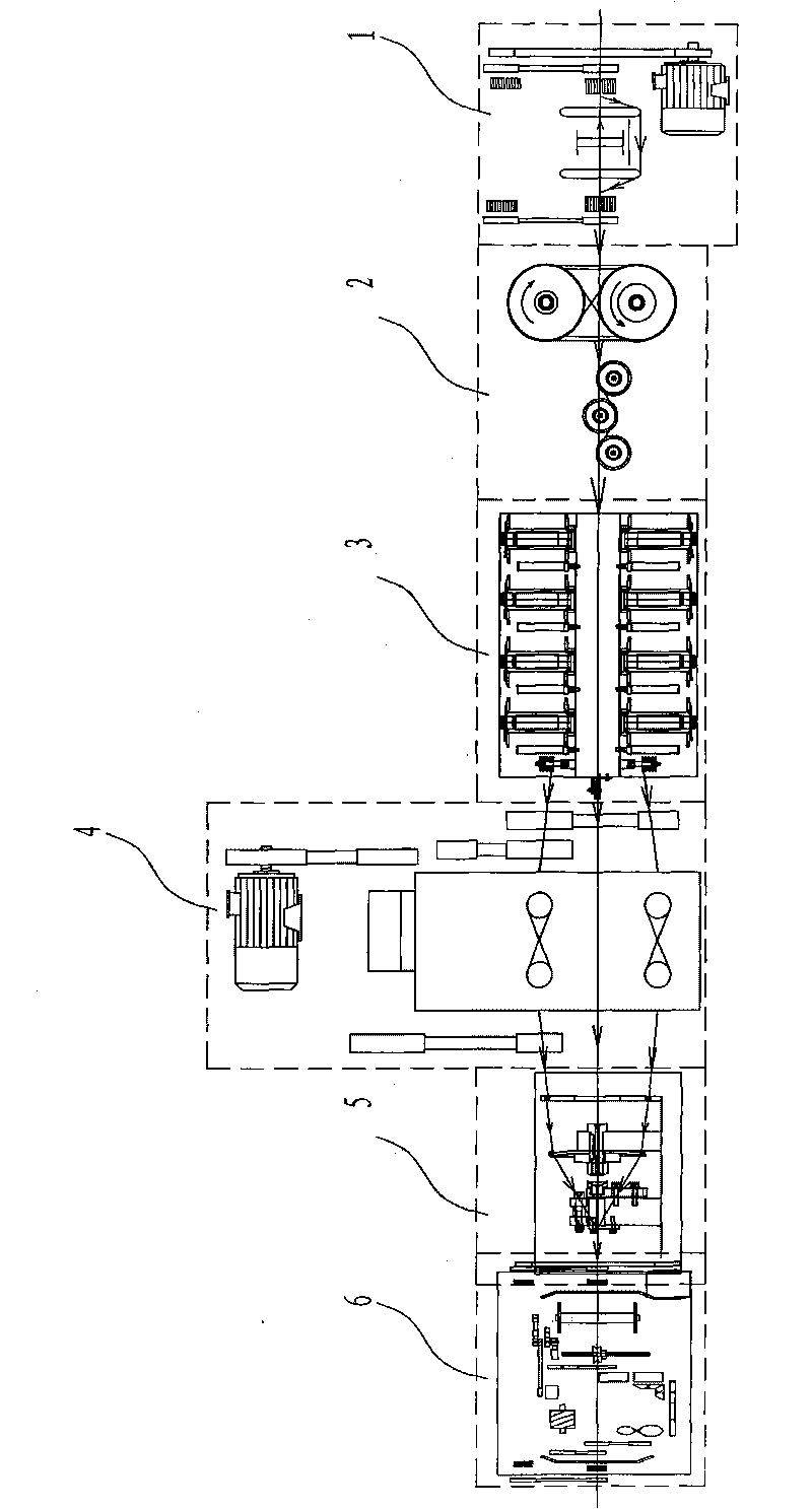
[0021] figure 1 As shown, the double-twist rope forming machine includes a core wire pay-off machine 1, a core wire tension mechanism 2, an upper thread pay-off mechanism 3, a monofilament pre-twisting machine 4, a wire collection mechanism 5, and a wire take-up machine 6 arranged in sequence. .

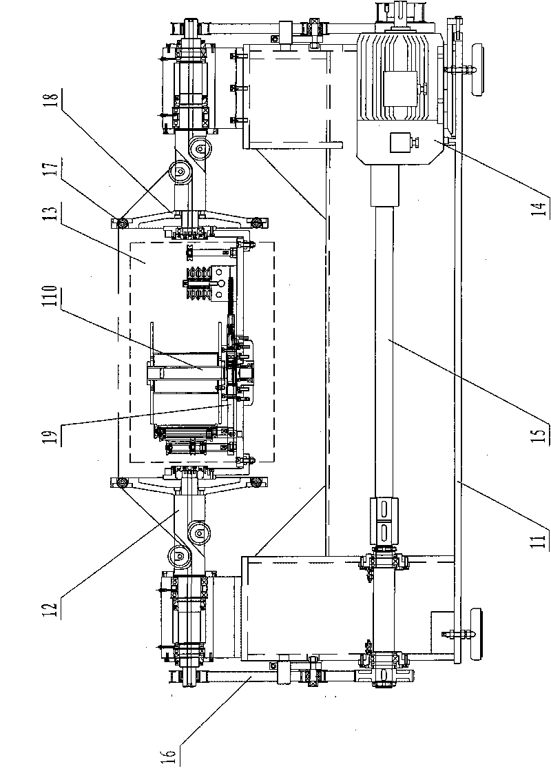
[0022] figure 2 As shown, the core wire pay-off machine 1 of the double-twist roping machine mainly includes a frame 11 and a flywheel shaft assembly 12 installed on the frame, a cradle assembly 13, a motor assembly 14, and a transmission shaft assembly 15. The axle assemblies are respectively installed on the left and right sides above the base, the cradle assembly is located in the middle of the core wire pay-off machine between the two flywheel shaft assemblies, the motor assembly is located under the right end of the base, and the transmission shaft assembly is located Below the seat back, the motor assembly drives the transmission shaft assembly through the transmission timin...


PUM


Abstract

The invention discloses a double twisting rope laying machine which comprises a core wire laying machine, a core wire tension mechanism, a surface wire laying mechanism, a single wire pre-twisting machine, a wire collecting mechanism and a wire-rewinding machine arranged sequentially, wherein the core wire tension mechanism comprises a broken wire detecting device, a wire roller, a tension control device and a tension detecting device; the core wire output tension is detected by the tension detecting device, and if the tension exceeds a set tension range, the core wire output tension is adjusted by the tension control device to realize accurate control of the core wire laying tension; and the single wire pre-twisting machine comprises a motor, a transmission component and a plurality of groups of rotor components which are arranged at the front surface and the back surface of a stand. Through the rotation of each group of rotor components, the single wire pre-twisting process is realized and the single wire stress is eliminated, thereby being favorable to twisting and forming, and finally, the twisted cords have good straightness, stable residual torsion and high product quality and is difficult to loose; and the specifications of the producible cords are 3+9+15*0.22, 3+9+15*0.175 and 0.25+(6+12)*0.22.

Description

technical field [0001] The invention relates to a double-twisting rope forming machine, which is a special mechanical device for producing steel cords for automobile tires and truck tires, and steel wire ropes for conveyor belts. The cord structures mainly produced are 3+9+15×0.22, 3 +9+15×0.175, 0.25+(6+12)×0.22. Background technique [0002] At present, the same type of double-twisting machine equipment is generally composed of a core wire pay-off machine, a rotary upper thread pay-off machine, a wire gathering mechanism, an external twisting machine, and a wire take-up machine. It mainly has the following deficiencies: 1. Core wire The control of the pay-off tension is mainly completed inside the core wire pay-off machine. Because the required pay-off tension is large and the tension fluctuates greatly, it is difficult to ensure that the pay-off tension from the full reel to the empty reel remains constant; 2. Because the upper thread pay-off adopts It is the method of r...

Claims


Application Information

Patent Timeline
Patent Type & Authority Applications(China)
IPC IPC(8): D07B3/00D02G3/36D02G3/44D02G3/48
Inventor 黄义华钱泽兰于正雄吴兰美蔡建军李辉
Owner 江苏泰隆机电科技有限公司
Why Eureka
Try Eureka