Bent connecting rod offset bent shaft mechanism and bent connecting rod offset bent shaft motor

A technology for bending connecting rods and crankshafts, which is applied in the field of crankshaft connecting rod transmission mechanism and its engine, and can solve problems such as cylinder excessive wear or knocking, loss of power, etc.

Inactive Publication Date: 2010-06-02
刘若丹
View PDF1 Cites 12 Cited by
  • Summary
  • Abstract
  • Description
  • Claims
  • Application Information

AI Technical Summary

Problems solved by technology

[0002] Now the center position of the crankshaft of the traditional piston engine is on the center line below the bore of the cylinder. The piston reciprocates in the cylinder, and the crankshaft is driven to rotate through the connecting rod. The rotation of the crankshaft makes the connecting rod produce a flexible and symmetrical swing arc; for a four-stroke engine , among the four strokes, only one stroke is the work combustion explosion stroke, that is, the starting point of the source power is that the top surface of the piston is stressed and concentrated on the pin of the piston connecting rod, and transmits power to the crankshaft through the connecting rod downward; the other three The starting point of the stroke power is just the opposite, that is, the starting point of the power is to transmit power (stroke power) to the connecting rod through the crankshaft crank to push the piston to complete the three strokes of exhaust, air intake and compression, and the existing engine piston connecting rod is on the crankshaft. In operation, the upper and lower dead centers are symmetrical, each of which is 180 degrees. Moreover, the up and down strokes of the piston are equal to the diameter of the crankshaft. In addition, in the power stroke of the working combustion explosion source, when the crankshaft turns to 90 degrees, the crankshaft torque is the largest. However, The inclination angle of the connecting rod is also the largest, the larger the inclination angle of the connecting rod, the greater the lateral horizontal component force generated by the piston, and the loss of part of the power will easily cause excessive wear or knocking of the cylinder

Method used


Image

  • Bent connecting rod offset bent shaft mechanism and bent connecting rod offset bent shaft motor
  • Bent connecting rod offset bent shaft mechanism and bent connecting rod offset bent shaft motor
  • Bent connecting rod offset bent shaft mechanism and bent connecting rod offset bent shaft motor

Examples


Embodiment Construction

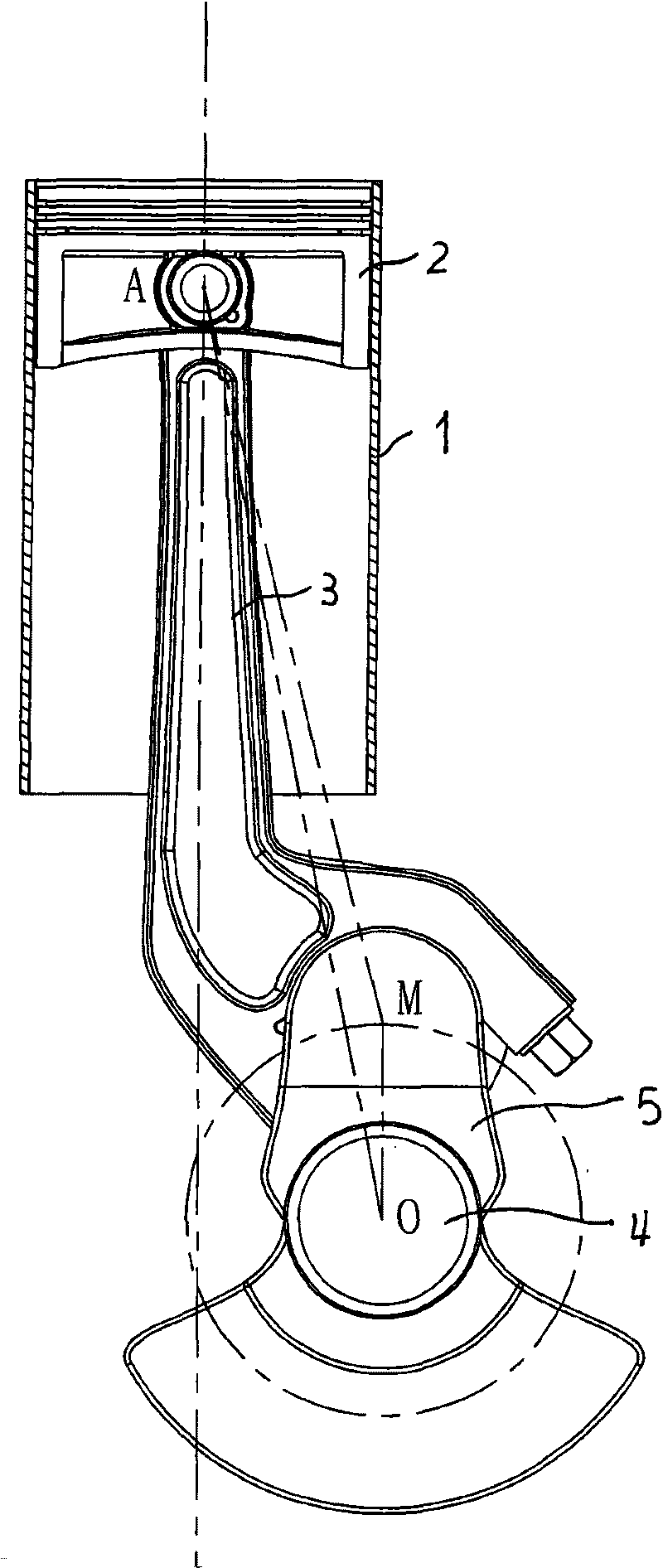
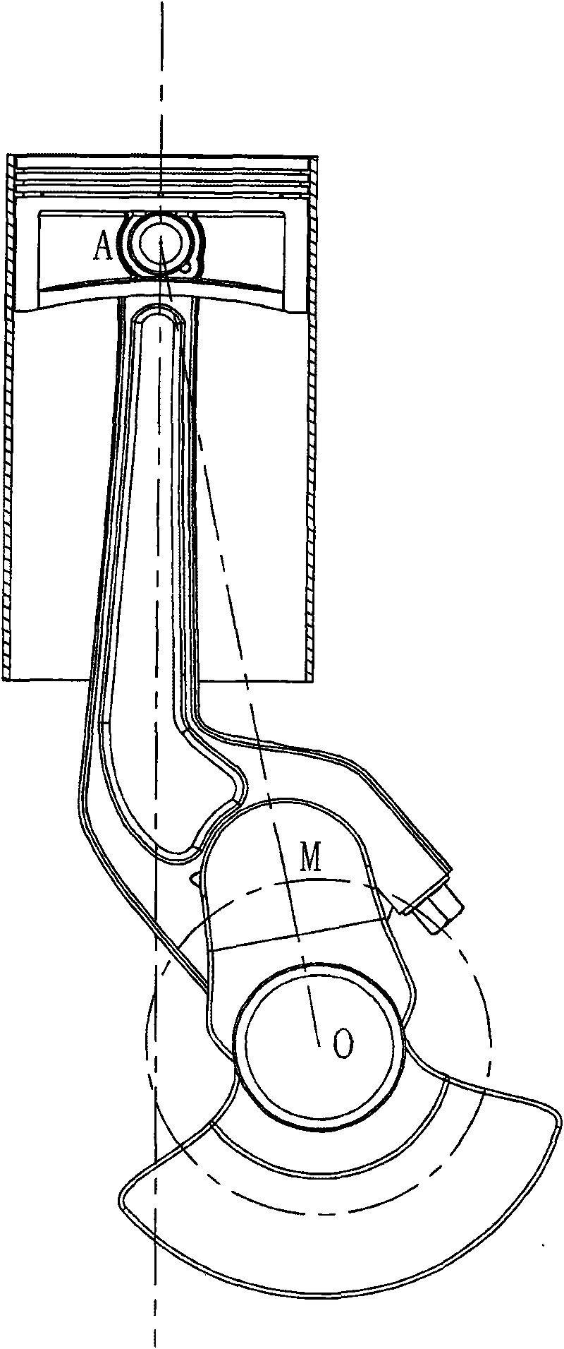
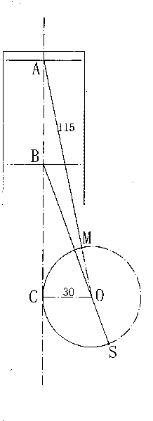
[0045] see figure 1 , this mechanism comprises cylinder 1, piston 2, connecting rod, crankshaft 4 and crank throw 5, intake cam 6 and intake rocker arm roller wheel 7, exhaust cam 8 and exhaust rocker arm roller wheel 9 (see Figure 18-2 ), the midpoint of the crankshaft circle deviates from the vertical centerline of the cylinder 1, and the offset is > 35% of the radius of the crankshaft. The connecting rod is a curved connecting rod 3, and the bending direction of the connecting rod in the mechanism is opposite to the offset direction of the crankshaft 4 (the bending direction of the connecting rod is according to figure 1 The arc direction of the middle connecting rod from the upper point to the lower point is counterclockwise). see Figure 22-3 , the bending shape of the connecting rod is that the connecting rod body bends to the outside of the connecting line between the two holes (piston shaft hole and crankshaft hole), and the bending direction of the connecting rod i...


PUM


Abstract

The invention discloses a bent connecting rod offset bent shaft mechanism and a bent connecting rod offset bent shaft motor, belonging to the bent shaft connecting rod mechanism of a piston explosive motor, and comprising a cylinder, a piston, a connecting rod, a bent shaft, a bent shaft crank, an inlet cam, an inlet rocker arm roller wheel, an outlet cam and an outer rocker arm roller wheel, wherein the circle center of the bent shaft is arranged in the mode of deviating from the median vertical line of the cylinder, and the offset is more than 35% of bent shaft radius; the connecting rod is the bent connecting rod, and the bending direction of the connecting rod is same with the rotation direction of the bent shaft; in the same cylinder, according to the cam shaft rotation direction, the intersection angle of the inlet cam is smaller than that of the outlet cam, and the difference of two intersection angles is equal to that 90 degrees subtract the dip angle difference of an upper dead center and a lower dead center on a 1/2 bent shaft. The invention changes the bent shaft position and is matched with a bent connecting rod, so that the offset bent shaft has the characteristics that the upper dead center and the lower dead center are asymmetric, and piston travel is bigger than bent shaft diameter; thus, engine torque is increased so as to effectively prolong torque duration as well as prolong burning and air inflow duration.

Description

technical field [0001] The invention relates to a transmission mechanism of a piston internal combustion engine, in particular to a crankshaft-connecting-rod transmission mechanism for increasing engine torque by changing the position of a crankshaft and cooperating with a curved connecting rod and the engine thereof. Background technique [0002] Now the center position of the crankshaft of the traditional piston engine is on the center line below the bore of the cylinder. The piston reciprocates in the cylinder, and the crankshaft is driven to rotate through the connecting rod. The rotation of the crankshaft makes the connecting rod produce a flexible and symmetrical swing arc; for a four-stroke engine , among the four strokes, only one stroke is the work combustion explosion stroke, that is, the starting point of the source power is that the top surface of the piston is stressed and concentrated on the pin of the piston connecting rod, and transmits power to the crankshaft...

Claims


Application Information

Patent Timeline
Patent Type & Authority Applications(China)
IPC IPC(8): F02B75/32F16C7/02F01L1/06F01L1/18
CPCF16C7/023
Inventor 刘若丹
Owner 刘若丹
Why Eureka
Try Eureka