
Automobile constant speed engine given load detection method

A technology that specifies load and engine, applied in the direction of engine test, internal combustion engine test, machine/structural component test, etc. It can solve the problem of damage to the vehicle or engine, high sensitivity to load error and speed error, and bench test to simulate road test load. Comprehensive error and other problems, to achieve the effect of improving detection accuracy and improving detection efficiency

Active Publication Date: 2011-10-26
HUAWEI TEHCHNOLOGIES CO LTD
View PDF1 Cites 0 Cited by
  • Summary
  • Abstract
  • Description
  • Claims
  • Application Information

AI Technical Summary

Problems solved by technology

[0002] There are two methods for testing the fuel economy of vehicles in use: one is the full-quality bench test of the vehicle to simulate the load of the road test. Under the condition of a small load of the engine at the position of the accelerator pedal at the specified speed and the position of the accelerator pedal is about 40% of the full load, the vehicle is tested. The fuel consumption per kilometer, this method has a large comprehensive error in bench test simulation road test load, and the sensitivity to load error and speed error is too high, so the accuracy of fuel economy detection cannot be guaranteed.
The other is the detection method of fuel consumption rate at constant speed and full load of automobiles, see the invention patent application number 200910205135.0 "Detection method of fuel consumption rate of automobiles at constant speed and full load". The minimum fuel consumption rate of the load, the defect is that for some in-use vehicles with excessive fuel supply of high-pressure fuel injection pumps or poor technical conditions, a longer detection may damage the vehicle or engine
[0003] Existing vehicle power detection is performed under the condition of full engine load. Although the power detection time is relatively short, it is still possible to damage the vehicle or engine in use under the full load of the larger engine rated torque.

Method used

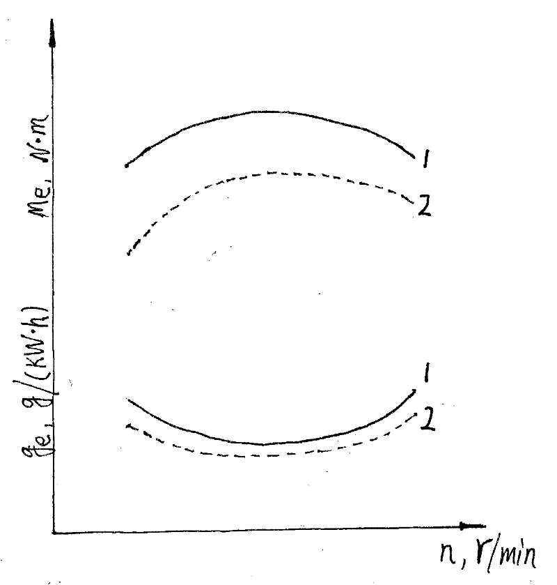

Image

  • Automobile constant speed engine given load detection method

Examples


Embodiment Construction

[0010] A domestic 1090 series truck constant-speed engine is loaded with a specified load to detect the fuel consumption rate and power performance to illustrate the specific implementation of the method: the engine rated power of this vehicle is 99kW / 2800r / min, and the maximum torque is 382Nm / 1700r / min , the direct transmission ratio is 1, the final reduction ratio is 6.33, the tire radius is 0.493m, and δ=0.75.

[0011] 1. Specified speed point V 1 is 55km / h, the engine accessory consumption torque is set at 0.07×382=26.74Nm directly at this speed point.

[0012] 2. Knowing the equivalent inertia of the chassis dynamometer and the vehicle’s neutral transmission system, the resistance of the vehicle’s neutral gear and the entire transmission system of the chassis dynamometer at the speed point of 55km / h is 760N, and the resistance power is 11.6kW. .

[0013] 3. Through the parameter calculation method, the ratio of the vehicle speed of the direct gear to the engine speed K=...


PUM


Abstract

The invention relates to an automobile constant speed engine specified load detection method, which defines the rotating speed range of the automobile speed under the engine rated torque and the full-load minimum fuel consumption rate when the high speed gear is engaged in a gearbox on a chassis dynamometer by an automobile, after the test and the calculation, the load constant force value of a power absorbing device of the engine defined load is determined at the defined automobile speed point, when the load working condition is defined by the engine delta rated torque, the load is controlled by the constant force of the power absorbing device, the accelerator is adjusted and stabilized, and the vehicular dynamic property and fuel economy are detected in the constant speed at the definedautomobile speed point, the method has good accuracy, validity and operability, meanwhile, the method can avoid the damages to the in-use vehicles or engines with worse technology condition, thereby increasing the detection safety.

Description

technical field [0001] This method is to put the car on the chassis dynamometer, put the gearbox in the high-speed gear, and the system loads the vehicle engine with a constant force load of the specified δ percentage rated torque, adjusts and stabilizes the accelerator pedal at the specified speed and constant speed to detect the fuel economy of the car or The power performance belongs to the technical field of vehicle bench test fuel economy or power performance detection method. Background technique [0002] There are two methods for testing the fuel economy of vehicles in use: one is the full-quality bench test of the vehicle to simulate the load of the road test. Under the condition of a small load of the engine at the position of the accelerator pedal at the specified speed and the position of the accelerator pedal is about 40% of the full load, the vehicle is tested. For the fuel consumption per kilometer, this method has a large comprehensive error in bench test simu...

Claims


Application Information

Patent Timeline
Patent Type & Authority Patents(China)
IPC IPC(8): G01M15/04G01M15/00
Inventor 吴明
Owner HUAWEI TEHCHNOLOGIES CO LTD
Learn More