Device and method for simultaneously monitoring flue gas particles and polluted gases on line

A technology for polluting gases and particulate matter, which is applied in the direction of measuring devices, particle suspension analysis, suspension and porous material analysis, etc., and can solve the problems of high maintenance costs, high cost, and uneconomical

Active Publication Date: 2011-05-18
TIANJIN TONGYANG TECH DEV +1
View PDF1 Cites 3 Cited by
  • Summary
  • Abstract
  • Description
  • Claims
  • Application Information

AI Technical Summary

Problems solved by technology

[0006] The disadvantage of the existing flue gas continuous monitoring system is that the polluted gas and particulate matter are measured by different equipment, and probes (or sampling heads) need to be installed in the flue openings respectively. The cost of the system is high, the installation and commissioning are cumbersome, and the maintenance cost high, not economical

Method used


Image

  • Device and method for simultaneously monitoring flue gas particles and polluted gases on line
  • Device and method for simultaneously monitoring flue gas particles and polluted gases on line
  • Device and method for simultaneously monitoring flue gas particles and polluted gases on line

Examples


Embodiment 1

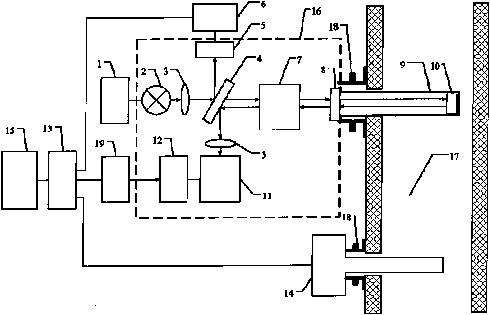
[0059] Such as figure 1 As shown, the present invention is a plug-in simultaneous online monitoring device for flue gas particulate matter and polluted gas. The spectrometer housing (16) is fixed to the flue (17) through the flange (18), and the flue gas emission parameter measurement unit (14) It is fixed with the flue (17) by the flange (18). The measurement signal of the flue gas emission parameter measurement unit (14) and the measurement signal of the spectrometer are connected to the AD converter (13) through a cable, and sent to the computer (15).

[0060] The light emitted by the light source (2) compresses the divergence angle through the lens (3), and is divided into two beams of light by the beam splitter (4). The preamplifier (6) is amplified and then sent to the AD converter to monitor and correct changes in the measured light intensity. The transmitted light of the beam splitter is collimated by the collimating mirror (7), and is incident on the flue (17) throu...

Embodiment 2

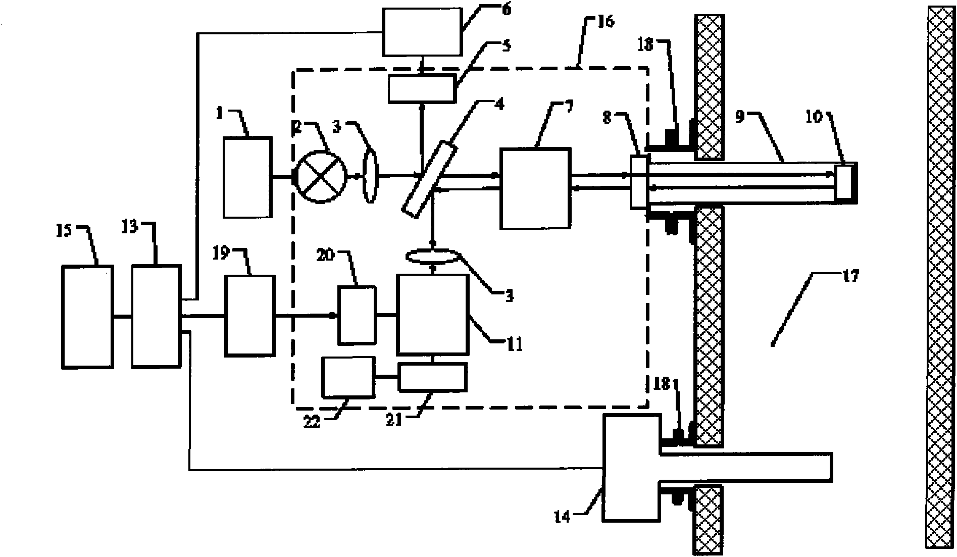
[0102] Such as figure 1 As shown, the present invention is a plug-in simultaneous on-line monitoring device for smoke particulate matter and polluted gas. The difference from Embodiment 1 is that in this embodiment, a planar grating is used as the dispersion element, and the measuring path detector (20) is used for single-channel signal detection, and the scanning of the dispersion wavelength is realized by the rotation of the grating driven by the micromotor (21) . The detector may be one of a photodiode, a photocell, and a photomultiplier tube. The micro motor (21) is driven by a micro motor driver (22).

[0103] Other parts are identical with embodiment 1.


PUM


Abstract

The invention relates to a device and method for simultaneously monitoring flue gas particles and polluted gases on line. A spectrometer (16) is fixed with a flue (17) via a flange (18), and a flue gas emission parameter measuring unit (14) is fixed with the flue (17) via the other flange (18). The measurement signal of the flue gas emission parameter measuring unit (14) and the measurement signal of the spectrometer are connected to an AD converter (13) through cable conductors and are sent to a computer (15). The method of the invention is the extension of a DOAS method, namely absorbing the rapid change components in the spectrum for online analysis of the polluted gases and absorbing the slow change components in the spectrum for online analysis of the particles after correcting slow change absorption of the polluted gases. The invention solves the technical problem of using the same light path to simultaneously monitor the polluted gases and the particles on line and reduces the system cost. Meanwhile, the probe inlets cut on the flue are lessened, thus the workloads of field installation, debugging and system maintenance in the future can be lightened.

Description

technical field [0001] The invention relates to an online monitoring method and device for flue gas, in particular to a device and method for simultaneous online detection of flue gas particulate matter and polluted gas based on a differential absorption spectrum analysis method. Background technique [0002] High concentrations of sulfur dioxide (SO2) emitted during coal and oil combustion 2 ), nitrogen oxides (NO x ) and particulate matter have caused serious harm to the environment and human health. All countries have formulated strict standards, norms and regulations to monitor, control and treat the emission of flue gas. [0003] The current continuous emission monitoring system (Continuous Emission Monitoring Systems, CEMS) of fixed pollution sources, the gaseous pollutants (SO 2 , NO x , middle-ring aromatics, etc.) and particulate matter are monitored with different equipment. On-line optical monitoring methods for particulate matter include opacity (turbidity) ...

Claims


Application Information

Patent Timeline
Patent Type & Authority Patents(China)
IPC IPC(8): G01N15/06
Inventor 杜振辉陈文亮徐可欣
Owner TIANJIN TONGYANG TECH DEV
Why Eureka
Try Eureka