Comprehensive insulation and voltage resistance testing device of electric connector

A technology for comprehensive testing of electrical connectors, applied in the direction of testing dielectric strength, etc., can solve problems such as insufficiency of insulation and pressure withstand time, low degree of automation of test operations, unreasonable grouping of contact couples, etc., to achieve fixed energization The effect of short time, high test efficiency and accurate test time control

Active Publication Date: 2010-06-02
CHINA NORTH IND GRP HANGLIAN TECH CO LTD
View PDF0 Cites 21 Cited by
  • Summary
  • Abstract
  • Description
  • Claims
  • Application Information

AI Technical Summary

Problems solved by technology

[0004] In order to solve the unreasonable grouping method of contact couples in the electrical connector to be tested in the prior art, cumbersome test steps, long fixed power-on total time, low test efficiency, low test operation automation, high labor intensity of manual operation, insulation and voltage resistance The pressurization time cannot be guaranteed, the test results are inaccurate and other deficiencies. The purpose of the present invention is to provide a kind of electric connector to be tested. It is a comprehensive test device for insulation and voltage resistance of electrical connectors with high degree, low labor intensity, no manual control of insulation and pressure resistance time, automatic control of pressure, precise test time control, and accurate test results.

Method used


Image

  • Comprehensive insulation and voltage resistance testing device of electric connector
  • Comprehensive insulation and voltage resistance testing device of electric connector
  • Comprehensive insulation and voltage resistance testing device of electric connector

Examples


Embodiment Construction

[0016] The present invention will be further described below in conjunction with accompanying drawing.

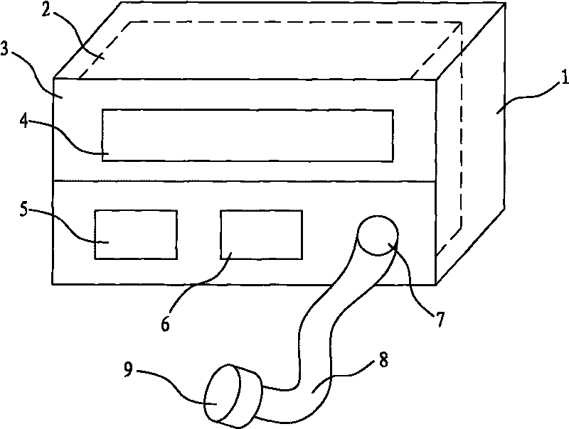
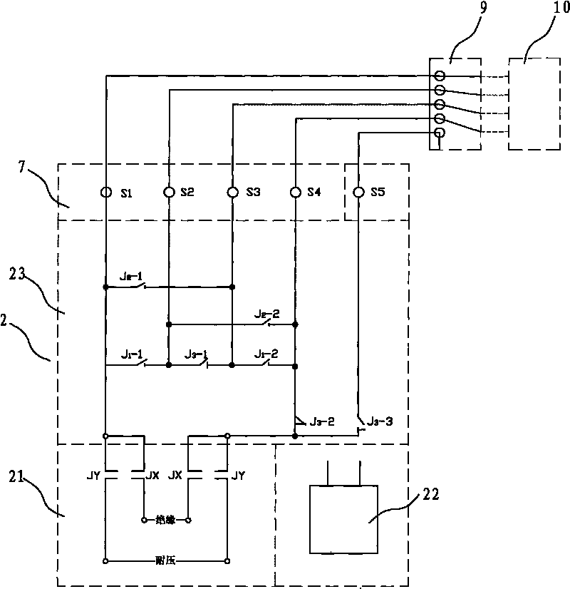
[0017] figure 1 , 2 The detection and control device shown mainly includes a test host 1, a test cable 8, and a conversion electrical connector 9. A control system 2 is arranged in the shell of the test host 1, a control panel 3 is arranged on the shell of the test host 1, and a control panel 3 is installed on the control panel 3. There is a display part 4, a starting device 5, an adjustment control device 6, and a common output interface 7. The common output interface 7 is connected to the conversion electrical connector 9 through the test cable 8, and the conversion electrical connector 9 is connected to the connector 10 of the point to be tested.

[0018] The control system 2 includes a test power supply 21, a sequence control circuit 22, a conversion execution circuit 23, and a common output interface 7. The test power supply 21 includes an insulation test power supply...


PUM


Abstract

The invention relates to a comprehensive insulation and voltage resistance testing device of an electric connector. Contact couples of electric conversion connector interfaces, which are connected with the electric connector to be tested, are divided into four test groups in a staggered row and staggered column mode; in the four test groups, a testing cable switches a common output interface connected with a testing power supply; a sequential control circuit controls the transverse short circuiting of the four test groups to test the transverse voltage of the contact couples, the longitudinal short circuiting of the four test groups to test the longitudinal voltage of the contact couples and the short circuiting of the four test groups to test voltage between the contact couples and a casing; and the comprehensive results of the testing voltage in the transverse direction and the longitudinal direction and between the contact couples and the casing are compared with insulation parameters and dielectric withstand voltage parameters which are set in a control system to complete the performance testing of an electric connector product to be tested. The invention has the advantages of few testing steps, short fixed conduction time, large testing quantity within unit time, high testing efficiency and testing degree of automation, accurate control of testing time, ensured voltage increase time of insulation and dielectric withstand voltage and accurate testing result.

Description

technical field [0001] The invention relates to the field of electrical connector testing devices, in particular to a testing device for testing the comprehensive performance of insulation and voltage resistance of electrical connectors. Background technique [0002] The insulation resistance and withstand voltage resistance of electrical connector products are the most basic electrical parameters to ensure the reliable operation of electrical connectors. Therefore, insulation resistance testers and withstand voltage testers must be used to detect electrical parameters such as insulation and withstand voltage of electrical connectors. , to determine whether the insulation resistance and withstand voltage between all contact couples and between the contact couple and the shell are qualified. Usually, the instrument needs to be replaced every time a parameter is measured. The speed is slow, the efficiency is low, and it is easy to make false detections and missed detections. ...

Claims


Application Information

Patent Timeline
Patent Type & Authority Applications(China)
IPC IPC(8): G01R31/12
Inventor 叶学俊张建军王守义印国富
Owner CHINA NORTH IND GRP HANGLIAN TECH CO LTD
Why Eureka
Try Eureka