
Automotive circuit detector

An automotive circuit and detector technology, applied in electronic circuit testing, instruments, measuring electricity and other directions, can solve the problems of long operation time, inconvenient operation, inability to operate, etc., and achieve small size, convenient use, safe and fast use. Effect

Inactive Publication Date: 2010-06-02
廖小安
View PDF7 Cites 5 Cited by
  • Summary
  • Abstract
  • Description
  • Claims
  • Application Information

AI Technical Summary

Problems solved by technology

[0002] At present, there are two ways to detect the car circuit. One is to use a conventional multimeter to detect. With this method, in the case of poor contact or aging of the car circuit, the test result shows normal, but it can no longer reflect the actual fault of the circuit. In this case, it is impossible to accurately detect the fault condition of the automobile circuit, which has great limitations in actual use; another way is to use a test lamp to detect the automobile circuit. The existing test lamp looks like a ballpoint pen. It consists of a transparent shell, a 12-volt small bulb, wires, and alligator clips. There is a pointed probe at the front of the test lamp. The 12-volt small bulb is installed in an insulating transparent shell. One end of the bulb is connected to the probe, and the other end is connected to the crocodile through the wire. clip connection
When using the test light, use the crocodile clip to ground first, then pick up the rubber wire with one hand, hold the wire under test with your middle finger, and hold the test lead with the other hand to insert the probe into the rubber wire. If there is current passing through, the bulb will light up; the voltage tested by this kind of test lamp is not very clear, the operation process takes a long time, it cannot be operated in some narrow places, it is easy to hurt hands during use, and it is extremely inconvenient to operate at night

Method used


Image

  • Automotive circuit detector
  • Automotive circuit detector
  • Automotive circuit detector

Examples


Embodiment Construction

[0014] The technology of the present invention will be further described below in conjunction with the accompanying drawings and embodiments.

[0015] The examples are not intended to limit the invention.

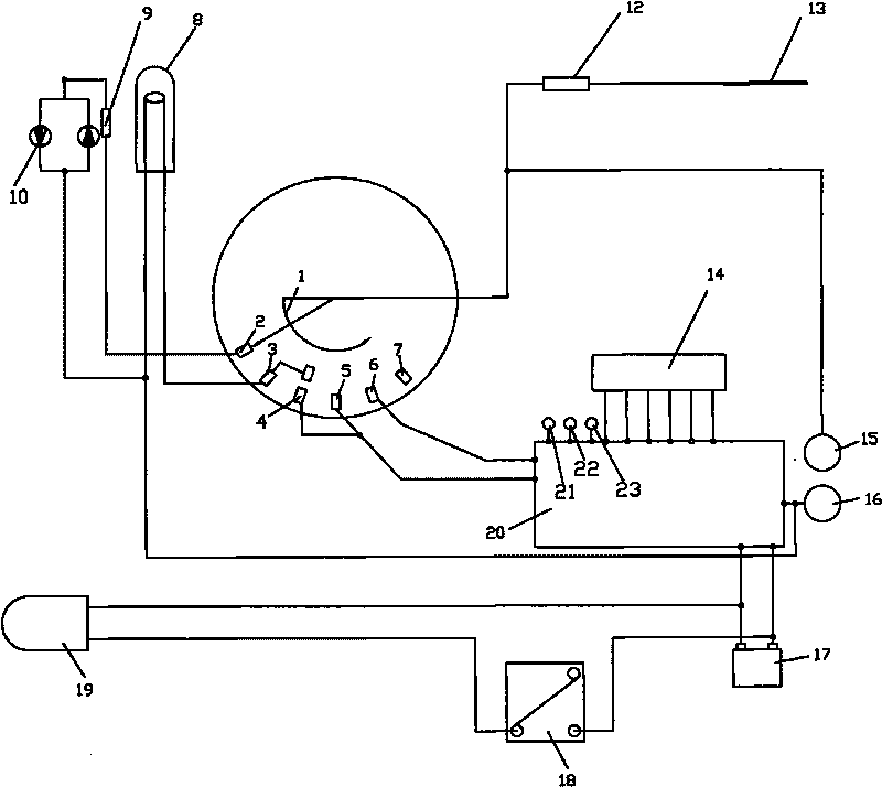
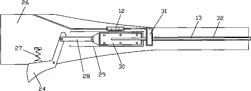
[0016] Such as figure 1 As shown, the automobile circuit tester of the present invention includes a housing 26, the housing is a small front and a large rear structure, a towing line hook 25 and a probe 13 are arranged on the top of the housing, and an illuminating lamp 19 is arranged at the front of the housing. , in the rear part of the housing from front to back, the sub-regions are arranged sequentially: trigger 24, electrodeless LED 10, test lamp 8, knob switch 1, LED gear 2 controlled by the knob switch, lamp test gear 3, lamp test and multimeter Gear 4, voltage gear 5, resistance gear 6, closed gear 7 multiple detection gears, lighting switch 18, multimeter use function keys: switching function key 21, backlight key 22, switching range key 23, display 14 and the tai...


PUM


Abstract

The invention discloses an automotive circuit detector, comprising a shell, a multimeter printed circuit board and a battery are arranged in the shell, the shell is a structure with small front part and big rear part, a towed-line hanger and a probe are arranged at the top part of the shell, a head lamp is arranged in front part of the shell, a trigger, an non-polarity light-emitting diode, a test lamp, a rotary switch, a plurality of detection gears controlled by the rotary switch, a lighting switch, multimeter use functional keys and a display are sequentially arranged at the rear part of the shell from forth to back in a zoning way, an anode pen and a cathode pen are arranged at the tail part of the shell, a return spring is arranged on the trigger, the trigger is compressed to push a connecting rod connected with the trigger, so as to drive the probe to be pushed out along a probe sliding groove in the shell. The automotive circuit detector can accurately detect the fault position of the automotive circuit, multiple gears are arranged to be suitable for detection of various faults, the usage is convenient, safe and rapid, and the detector can be well suitable for various maintaining environments, thereby being applied to maintenance of the automotive circuit and being applied to relative decoration relative to the automotive circuit.

Description

technical field [0001] The invention relates to a detection instrument for an automobile internal circuit, in particular to an automobile circuit detection instrument. Background technique [0002] At present, there are two ways to detect the car circuit. One is to use a conventional multimeter to detect. With this method, in the case of poor contact or aging of the car circuit, the test result shows normal, but it can no longer reflect the actual fault of the circuit. In this case, it is impossible to accurately detect the fault condition of the automobile circuit, which has great limitations in actual use; another way is to use a test lamp to detect the automobile circuit. It consists of a transparent shell, a 12-volt small bulb, wires, and alligator clips. There is a pointed probe at the front of the test lamp. The 12-volt small bulb is installed in an insulating transparent shell. One end of the bulb is connected to the probe, and the other end is connected to the crocod...

Claims


Application Information

Patent Timeline
IPC IPC(8): G01R31/28G01R31/02
Inventor 廖小安
Owner 廖小安
Learn More