Driving system of wheel-drive type hydrostatic transmission hybrid vehicle

A hybrid vehicle and wheel-side drive technology is applied in the field of the transmission system of the hybrid vehicle, which can solve the problems of unreasonable distribution of the axle structure and inflexible driving torque structure layout of the driving wheels, etc. Shortened design cycle and high efficiency

Active Publication Date: 2010-06-09
哈尔滨工业大学高新技术开发总公司
View PDF0 Cites 10 Cited by
  • Summary
  • Abstract
  • Description
  • Claims
  • Application Information

AI Technical Summary

Problems solved by technology

[0003] Aiming at the problems that the axle structure of the hydrostatic transmission hybrid vehicle cannot reasonably distribute the driving torque of the driving wheels and the structural layout is inflexible, the present invention proposes a wheel-side driven hydrostatic transmission hybrid vehicle transmission system

Method used


Image

  • Driving system of wheel-drive type hydrostatic transmission hybrid vehicle
  • Driving system of wheel-drive type hydrostatic transmission hybrid vehicle

Examples


specific Embodiment approach 1

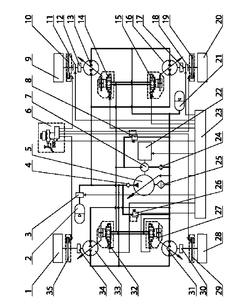
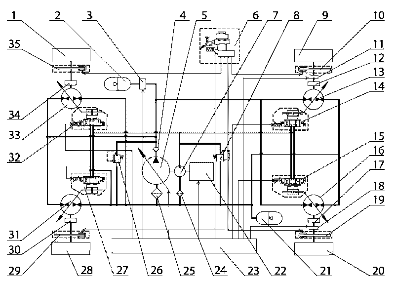
[0016] Specific implementation mode one: combine figure 1 Describe this embodiment, present embodiment comprises right front wheel 1, left front wheel 28, right rear wheel 9, left rear wheel 20, right rear wheel reducer 12, left rear wheel reducer 17, left front wheel reducer 30, right front Wheel reducer 34, right rear wheel clutch 11, left rear wheel clutch 18, friction brake controller assembly 6, right rear wheel friction brake 10, left rear wheel friction brake 19, left front wheel friction brake 29 and right front wheel friction brake Brake 35; also includes power element, right rear wheel hydraulic pump / motor 13, left rear wheel hydraulic pump / motor 16, left front wheel hydraulic pump / motor 31, right front wheel hydraulic pump / motor 33, high pressure hydraulic accumulator 2 , low pressure hydraulic accumulator 21, left front wheel hydraulic pump / motor variable device 27, right rear wheel hydraulic pump / motor variable device 14, left rear wheel hydraulic pump / motor varia...

specific Embodiment approach 2

[0026]Specific implementation mode two: combination figure 1 Describe this embodiment, the difference between this embodiment and specific embodiment 1 is that a power oil circuit relief valve 26 is added, which is connected between the oil outlet of the constant pressure variable pump 5 and the inlet and outlet of the low pressure hydraulic accumulator 21 There is a power oil relief valve 26, the oil inlet of the power oil relief valve 26 is connected to the oil outlet of the constant pressure variable pump 5, and the oil discharge port of the power oil relief valve 26 is connected to the low-pressure hydraulic accumulator 21 The oil inlet and outlet connections. Other compositions and connection methods are the same as those in Embodiment 1.

specific Embodiment approach 3

[0027] Specific implementation mode three: combination figure 1 Describe this embodiment, the difference between this embodiment and the specific embodiment is that a control oil circuit relief valve 8 is added, and a control valve is connected between the oil outlet of the quantitative pump 7 and the inlet and outlet of the low-pressure hydraulic accumulator 21. The oil relief valve 8 controls the connection between the oil inlet of the oil relief valve 8 and the oil outlet of the quantitative pump 7, and controls the oil discharge port of the oil relief valve 8 and the oil inlet and outlet of the low-pressure hydraulic accumulator 21 connect. Other compositions and connection methods are the same as those in Embodiment 1.


PUM


Abstract

The invention discloses a driving system of a wheel-drive type hydrostatic transmission hybrid vehicle, relates to the field of vehicle transmission, and aims to solve the problems that the driving torque of a driving wheel cannot be allocated reasonably and the structural layout is not flexible because the hydrostatic transmission hybrid vehicle uses an axle structure. A high-pressure hydraulic accumulator is connected with oil inlets of a constant-pressure variable pump and wheel hydraulic pumps/motors through an electromagnetic switching valve; the oil outlet of a fixed delivery pump is connected with oil inlets of wheel hydraulic pump/motor variable devices; a low-pressure hydraulic accumulator is connected with the oil outlets of the constant-pressure variable pump, the fixed delivery pump, the wheel hydraulic pumps/motors and wheel hydraulic pump/motor variable devices; the wheel hydraulic pump/motor variable devices control the wobble plates of the wheel hydraulic pumps/motors;and the wheel hydraulic pumps/motors are connected with input shafts of wheel reducers; a central controller controls power elements, the wheel hydraulic pump/motor variable devices, the electromagnetic switching valve, a wheel clutch, and a friction braking controller group which controls a friction brake. The maximum discharge capacity of the rear wheel hydraulic pump/motor is greater than thatat the front wheel hydraulic pump/motor; the reduction ratio of the rear wheel reducer is greater than that of the front wheel reducer. The driving system has the advantages of simplifying transmission, facilitating flexible layout, and being suitable for various vehicles.

Description

technical field [0001] The invention relates to the field of vehicle transmission, in particular to a transmission system of a hybrid vehicle. Background technique [0002] The traditional vehicle transmission system is composed of the engine as an independent power source, through the gearbox, the main drive shaft, the transmission axle and the drive wheel. In the process of frequent starting and braking of the vehicle, its fuel efficiency is low and harmful exhaust emissions increase. As the number of vehicles increases year by year, it has put enormous pressure on the energy and environment of our country and the world. The hybrid solution can recover the wasted braking energy of traditional vehicles, so that the engine can work more under economical conditions, with obvious energy-saving and emission-reduction effects. The current hydrostatic transmission hybrid scheme still uses the axle structure in the traditional vehicle drive train, and it cannot reasonably distri...

Claims


Application Information

Patent Timeline
Patent Type & Authority Applications(China)
IPC IPC(8): B60K6/52
CPCY02T10/6265Y02T10/62
Inventor 姜继海王昕
Owner 哈尔滨工业大学高新技术开发总公司
Why Eureka
Try Eureka