Safe pressure relief device

A pressure relief device and a safe technology, applied in the components of the pumping device for elastic fluid, liquid variable capacity machinery, pump control and other directions, can solve the problems of motor coil burning, damage to related parts, high pressure shock, etc. Achieve the effect of low manufacturing cost, simple structure, easy assembly and maintenance

Inactive Publication Date: 2010-06-09
XIN WANG ENTERPRISE CO LTD
View PDF0 Cites 4 Cited by
  • Summary
  • Abstract
  • Description
  • Claims
  • Application Information

AI Technical Summary

Problems solved by technology

[0004] However, when using a vacuum pump that can generate strong suction, it is necessary to pay attention to whether there is a problem of high-pressure gas introduction. For example, during the forming operation, if the film ruptures and the high-pressure gas in the system directly rushes into the vacuum pump, in addition to directly affecting the relevant In addition to the high-pressure shock caused by the mechanism, the speed of the vacuum pump will increase instantly, which will easily lead to vibration, high heat, etc., which will lead to subsequent problems such as shortened service life of the vacuum pump, burnt motor coils, etc.
[0005] In view of the problem that when the vacuum pump introduces high-pressure gas, it will cause damage to related parts, the inventor has developed a safety pressure relief device to prevent high-pressure gas from directly rushing into the vacuum pump and causing damage

Method used


Image

  • Safe pressure relief device
  • Safe pressure relief device
  • Safe pressure relief device

Examples


Embodiment Construction

[0027] According to the technical means of the present invention, the implementation modes suitable for the present invention are listed below and described in conjunction with the drawings as follows:

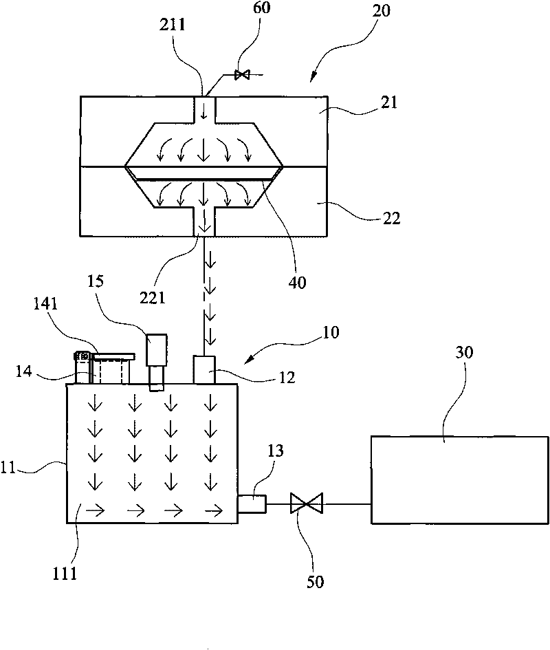
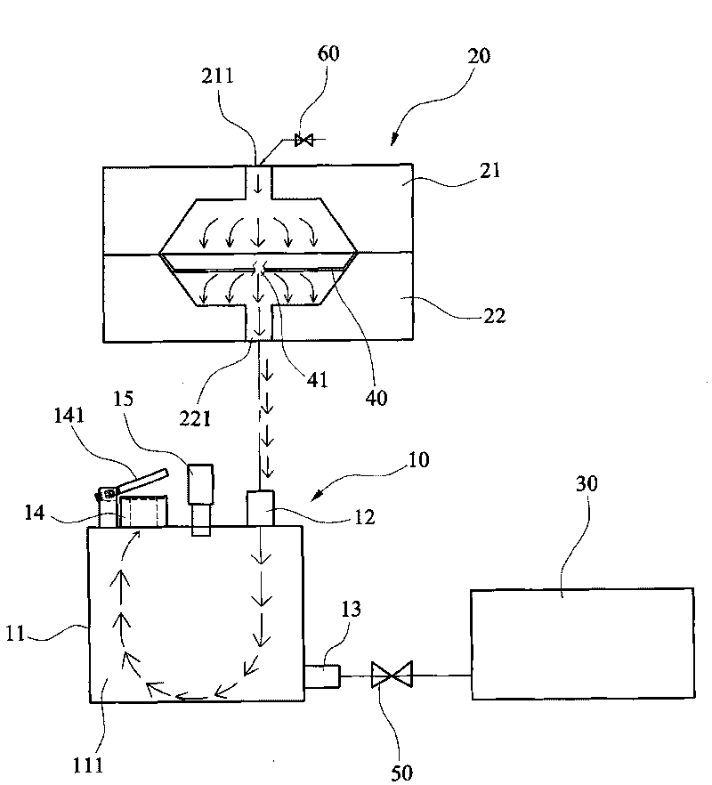
[0028] see figure 1 , is a schematic diagram of the erection configuration of the first embodiment of the present invention. The figure discloses a safety pressure relief device 10 that is connected in series between the high pressure forming system 20 and the vacuum pump 30 .

[0029] The high pressure forming system 20 includes an upper mold 21 clamped on the film 40 and a lower mold 22, wherein the upper mold 21 provides high-pressure gas to push the film 40, and the lower mold 22 includes a negative pressure end 221 for vacuuming , so that the film 40 can be closely attached to the lower mold 22 for forming.

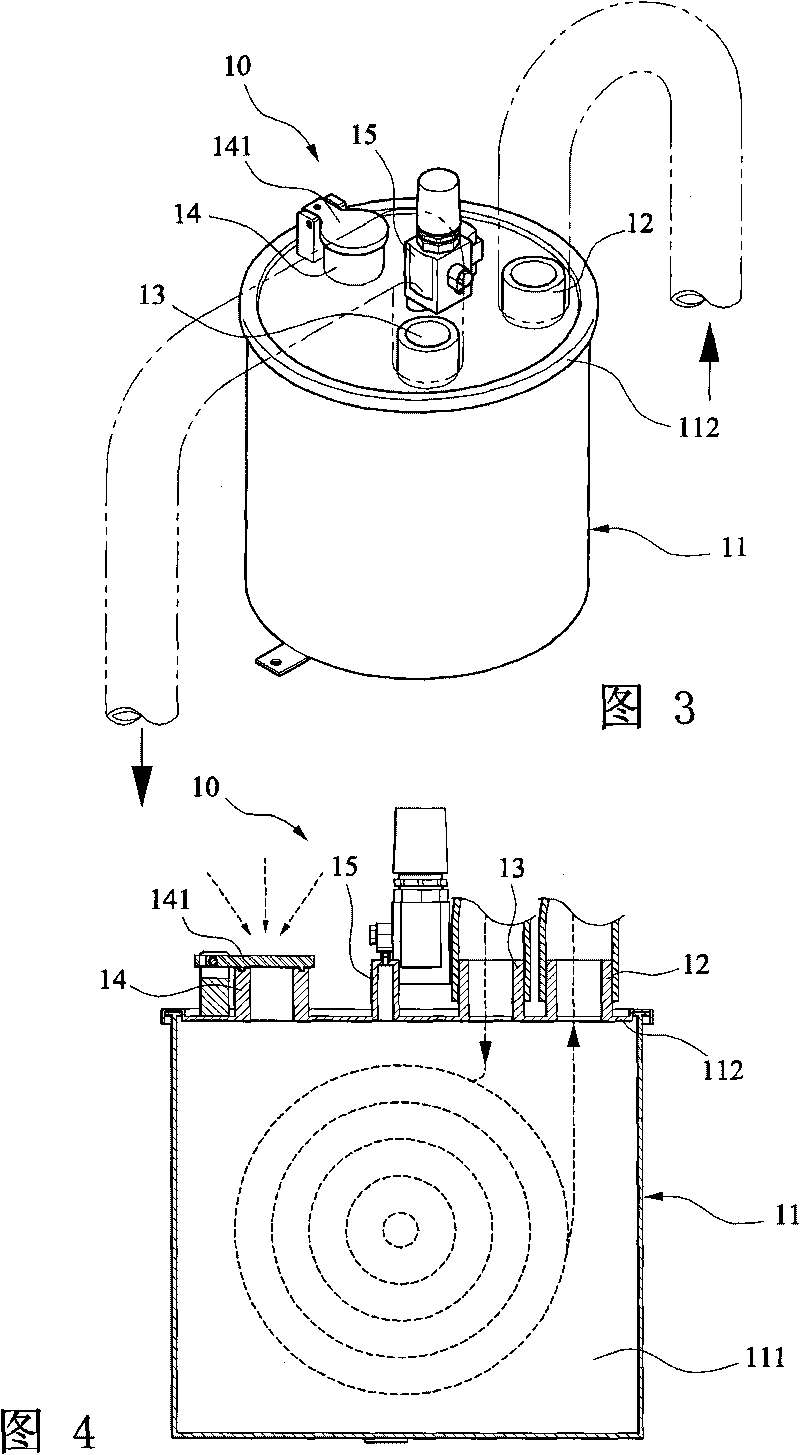
[0030] The safety pressure relief device 10 has a hollow cylinder 11 , and the cylinder 11 contains an accommodating space 111 . A suction port 12 connected to the...


PUM


Abstract

The invention relates to a safe pressure relief device for being connected in series between a negative pressure end of a high-pressure forming system and a vacuum pump. The safe pressure relief device is provided with a hollow cylinder body, wherein the cylinder body is respectively provided with a sucking opening connected with the negative pressure end of the system, an exhaust opening connected with the vacuum pump, a safe pressure relief opening and a one-way valve covering a safe pressure relief opening. Once the condition of film breakage is generated, the high-pressure gas released by the system is directly exhausted from the safe pressure relief opening and can not directly enter the vacuum pump to cause system failure.

Description

field of invention [0001] The invention provides a technology for protecting a vacuum pump, especially a safety pressure relief device installed at the front end of the vacuum pump in a high-pressure forming system, which can prevent high-pressure gas from directly rushing into the vacuum pump. Background technique [0002] High-pressure (film) forming machine is a processing system that utilizes high-pressure gas combined with the negative pressure principle of vacuum adsorption to enable the film to be quickly attached and formed; the existing film forming method is to place the film on the mold of the system, after Heat to the temperature required to soften the film, then vacuum the lower surface of the film and the upper surface of the mold and apply high pressure to the upper surface of the film, so that the film is attached to the surface of the mold to facilitate film forming. [0003] The vacuum state of the mold under the system is mainly due to the operation of a v...

Claims


Application Information

Patent Timeline
IPC IPC(8): F04B53/00F04B49/10F04C29/00F04C28/28
Inventor 王贵戊
Owner XIN WANG ENTERPRISE CO LTD
Why Eureka
Try Eureka