Compound gear

A compound gear and gear technology, applied in the field of spiral bevel gears, can solve the problems of uneven load on the tooth surface, small number of cog teeth, high impact noise, etc., and achieve long service life, small load per tooth, and high meshing accuracy Effect

Inactive Publication Date: 2010-06-09
JIANGSU AIRSHIP GEAR
View PDF0 Cites 3 Cited by
  • Summary
  • Abstract
  • Description
  • Claims
  • Application Information

AI Technical Summary

Problems solved by technology

[0003] The present invention mainly aims at the deficiencies in the prior art due to the difference in direction of rotation of the cog-type coupling teeth, the small number of protruding cog teeth, uneven load on the tooth surface, laborious gear shifting, high impact noise, and easy damage, etc., and proposes a An integrated compound structure, using straight teeth with involute tooth shape as the combined teeth, each tooth bears the load evenly, easy to shift, low noise, and a compound gear that does not distinguish the direction of rotation

Method used


Image

  • Compound gear
  • Compound gear
  • Compound gear

Examples


Embodiment Construction

[0016] The present invention will be further described below according to accompanying drawing.

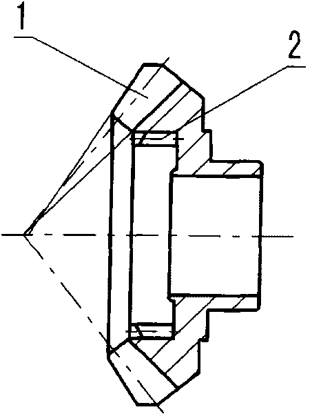
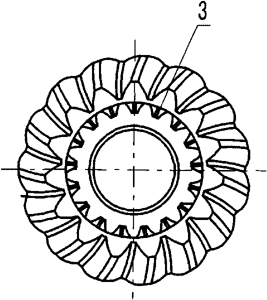
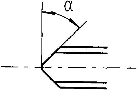
[0017] attached figure 1 The compound gear shown is composed of a spiral bevel gear 1 and an involute combined gear 2. The involute coupling gear 2 is set in the inner cavity of the spiral bevel gear and is coaxial. The involute coupling teeth are straight teeth, the tooth surface is parallel to the axis, the right end of the tooth is engaged with the inner end surface of the spiral bevel gear 1, and the left end of the tooth is set like image 3 For the symmetrical chamfer shown, the chamfer in this embodiment is 70°. The involute joint gear 2 is recessed in the middle of the spiral bevel gear 1, and its diameter is smaller than the root circle of the small end of the spiral bevel gear 1. This implementation is a compound gear used in the reverse gear mechanism of a car. The spiral bevel gear in this gear still maintains the original structural parameters. Only the inner cavit...


PUM


Abstract

The invention discloses a compound gear, which is formed by a spiral bevel gear and a combined involute gear. The combined involute gear is arranged in the inner cavity of the spiral bevel gear, is coaxial with the spiral bevel gear, and starts from the left end surface of the spiral bevel gear and ends up in the inner end surface thereof. The invention uses a built-in combined involute gear structure; the combined gear has more teeth and dispersed load, and is manufactured without considering turning directions, thus reducing paired stock removal and being favor of lowering production cost.The combined involute gear end is provided with a double chamfer, thus facilitating gear shift, reducing impact force of gear shift and lowering noise.The invention is especially used as a gear for controlling the output direction in a reverse mechanism of a vehicle.

Description

technical field [0001] The invention relates to a gear, in particular to a spiral bevel gear with involute joint teeth inside. Background technique [0002] Motor boats, three-wheeled motorcycles, marine gearboxes and engineering drilling rigs and other mobile equipment are equipped with a reverse gear mechanism. The traditional reverse gear mechanism consists of a jaw clutch, which controls the left jaw output spiral bevel gear and the right jaw output respectively. The spiral bevel gear meshes with the input spiral bevel gear to realize the positive and negative rotation of the output shaft. The above two kinds of output spiral bevel gears with different directions of rotation are all combined gears that are connected by spiral bevel gears and interlocking coupling teeth. The spiral bevel gears in the combined gear are exactly the same, except that the interlocking combined teeth have left and right rotations. The jaw-type output arc gear of the prior art can meet the re...

Claims


Application Information

Patent Timeline
Patent Type & Authority Applications(China)
IPC IPC(8): F16H55/17
Inventor 金九如仲志全姜天平
Owner JIANGSU AIRSHIP GEAR
Why Eureka
Try Eureka