Sun sensor simulator for satellite closed cycle simulation test
A solar sensor and closed-loop simulation technology, applied in the field of satellite testing, can solve the problems of complex operation and high cost, and achieve the effects of flexible control, reduced development cost, and shortened development cycle.
- Summary
- Abstract
- Description
- Claims
- Application Information
AI Technical Summary
Problems solved by technology
Method used
Image
Examples
specific Embodiment approach 1
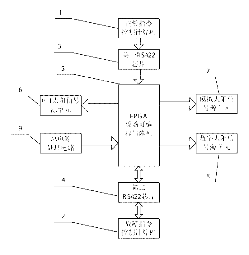
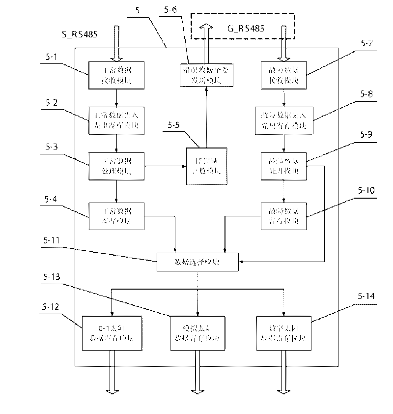
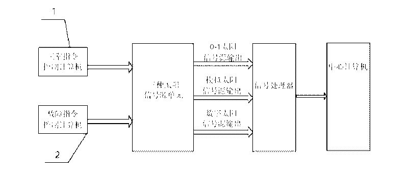
[0014] Specific implementation mode one: the following combination Figure 1-Figure 3 To illustrate this embodiment, this embodiment consists of normal command control computer 1, fault command control computer 2, first RS422 chip 3, second RS422 chip 4, FPGA field programmable gate array 5, 0-1 solar signal source unit 6 , an analog sun signal source unit 7, a digital sun signal source unit 8 and a total power processing circuit 9,
[0015] The control signal output end of the normal command control computer 1 connects the normal command control signal input end of the FPGA field programmable gate array 5 through the first RS422 chip 3, and the fault command control signal input and output end of the FPGA field programmable gate array 5 passes through the second The RS422 chip 4 is connected to the failure signal output and input terminals of the fault command control computer 2; the 0-1 solar control signal output terminal of the FPGA field programmable gate array 5 is conne...
specific Embodiment approach 2
[0025] Specific implementation mode two: the following combination Figure 4 and Figure 7 To describe this embodiment, the difference between this embodiment and Embodiment 1 is that the 0-1 sun signal source unit 6 is composed of a first power processing circuit 6-1, a voltage conversion chip 6-2, and a reverse decay circuit 6 -3, composed of five first relays 6-4 and five first voltage-controlled current source circuits 6-5,
[0026] The power output end of the first power processing circuit 6-1 is connected to the power input end of the voltage conversion chip 6-2, and the power output end of the voltage conversion chip 6-2 is connected to the power input end of the reverse attenuation circuit 6-3, and the reverse attenuation The power output end of the circuit 6-3 is connected to the power input ends of five first relays 6-4, and the power output end of each first relay 6-4 is connected to the power input end of a first voltage-controlled current source circuit 6-5 ; Th...
specific Embodiment approach 3
[0036] Specific implementation mode three: the following combination Figure 5 To illustrate this embodiment, the difference between this embodiment and Embodiment 2 is that the simulated sun signal source unit 7 is composed of a digital-to-analog conversion chip 7-1 and four second voltage-controlled current source circuits 7-2,
[0037] The digital signal input end of the digital-to-analog conversion chip 7-1 is connected to the analog sun control signal output end of the FPGA field programmable gate array 5, and the analog signal output end of the digital-to-analog conversion chip 7-1 is connected to four second voltage-controlled current source circuits 7-2's power input. Other components and connections are the same as those in Embodiment 2.
[0038]The simulated sun signal source unit 7 is different from the 0-1 sun signal source unit 6, and what the simulated sun signal source unit 7 needs to obtain is a continuous output of current. Therefore, a digital-to-analog con...
PUM
 Abstract
Description
Claims
Application Information
 - R&D
- Intellectual Property
- Life Sciences
- Materials
- Tech Scout
- Unparalleled Data Quality
- Higher Quality Content
- 60% Fewer Hallucinations
Browse by: Latest US Patents, China's latest patents, Technical Efficacy Thesaurus, Application Domain, Technology Topic, Popular Technical Reports.
© 2025 PatSnap. All rights reserved.Legal|Privacy policy|Modern Slavery Act Transparency Statement|Sitemap|About US| Contact US: help@patsnap.com


