Unlock instant, AI-driven research and patent intelligence for your innovation.

Circuit and method for mixing signals

A mixed-signal and signal technology, applied in electrical components, improving frequency converters, modulation transfer, etc., can solve problems such as reducing system performance, and achieve the effect of improving performance and reducing amplitude mismatch or phase error

Inactive Publication Date: 2010-06-09
BEKEN CORP
View PDF0 Cites 6 Cited by
  • Summary
  • Abstract
  • Description
  • Claims
  • Application Information

AI Technical Summary

Problems solved by technology

When multiple correlator configurations are used in devices (such as separate I and Q paths), phase shifts, amplitude mismatches, and / or other possible sources of non-idealities can degrade system performance

Method used


Image

  • Circuit and method for mixing signals
  • Circuit and method for mixing signals
  • Circuit and method for mixing signals

Examples


Embodiment Construction

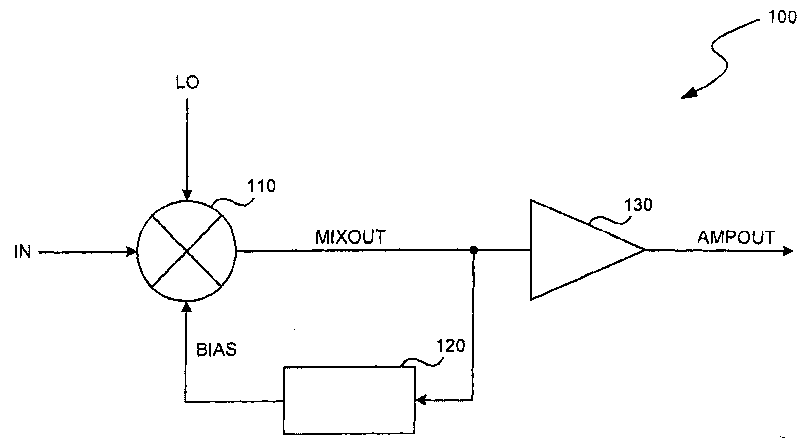
[0019] figure 1 is a block diagram of the mixer circuit 100 . As shown, the circuit 100 includes a mixer 110 , a bias circuit 120 and an amplifier 130 . In a specific embodiment, circuit 100 is used to provide amplifier output signal AMPOUT by mixing input signal IN with local oscillator signal LO. Application-specific integrated circuits (ASICs), discrete components, mixed-signal integrated circuits, and the like may all be used in circuit 100 . Circuit 100 may also include analog circuits, digital circuits, and / or mixed analog and digital circuits.

[0020] Circuit 100 may be used in receivers, transmitters, radio transceivers (eg, cellular phones, cordless phones, wireless network cards, wireless transceivers, etc.). The circuit 100 can be used in any device or system in which a mixer can be used. For example, the circuit 100 may be used in wireless communication devices, wired communication devices, interface systems, computing devices, optical media devices, embedded ...


PUM


Abstract

The invention discloses a circuit and a method for mixing signals in a communication system. The circuit for mixing signals comprises a same phase mixer, an orthogonal mixer and a biasing circuit. The same phase mixer utilizes the signal of a same phase local oscillator to mix input signals. The orthogonal mixer utilizes the signal of the orthogonal local oscillator to mix input signals. The signal of the orthogonal mixer differs 90-degree phase with that of the same phase local oscillator. The biasing circuit provides DC bias to the same phase mixer and the orthogonal mixer so as to balance output thereof.

Description

technical field [0001] The present invention relates to a circuit and method for mixing signals in a communication system. Background technique [0002] Mixer circuits are often used in communication systems. For example, mixer circuits and methods may be used to modulate a data component of a carrier, demodulate a data component from a modulated signal, or convert a signal from one frequency band to another, etc. Mixer circuits may be used in receivers, transmitters, radio transceivers (eg, wireline phones, cable boxes, cable modems, cordless phones, cellular phones, ham radios, television and optical transceivers, etc.), and other devices. [0003] In communication systems, non-ideal physical layers can adversely affect clock signal recovery. In a device, these non-idealities include propagation delay, signal attenuation, noise, DC compensation, nonlinearity, and quantization error. These non-idealities can degrade system performance when multiple correlator configurati...

Claims


Application Information

Patent Timeline
IPC IPC(8): H03D7/18
CPCH03D7/1466H03D7/1458H03D2200/0088H03D2200/0043H03D2200/0025H03D7/165H03D7/1483H03D2200/0047H03D7/1433H03D7/1441
Inventor 郭大为王俭
Owner BEKEN CORP
Features
  • R&D
  • Intellectual Property
  • Life Sciences
  • Materials
  • Tech Scout
  • Unparalleled Data Quality
  • Higher Quality Content
  • 60% Fewer Hallucinations
Learn More