Led illumination device using diffraction member

A technology of LED lighting and components, which is applied in the direction of lighting devices, parts of lighting devices, diffuser elements, etc., which can solve the problems of adding electrodes, reducing the amount of light emitted, and large resistivity, so as to reduce the influence of shading and increase the degree of freedom in design , the effect of suppressing fever

Inactive Publication Date: 2010-06-09
ABEL SYST
View PDF3 Cites 6 Cited by
  • Summary
  • Abstract
  • Description
  • Claims
  • Application Information

AI Technical Summary

Problems solved by technology

However, since the electrode is attached to the surface of the element, and the electrode blocks light, the improvement of the output efficiency of the light to the outside and the large light quantization due to the increase in area are hindered.
However, in order to reduce the influence of light shielding, if the area of ​​the electrode is reduced by a certain value or more compared to the area of ​​the element, the same electric field cannot be applied to the entire element, and the light emission itself will also decrease.
Therefore, even if the area of ​​the element is increased in order to obtain a large amount of light, when it is to be surface-emitting, the area of ​​the electrode must be increased as a result, and a large amount of light cannot be emitted to the outside due to the light-shielding effect of the electrode.
In addition, in view of such disadvantages, it is considered to use a transparent electrode such as ITO, but the resistivity of the transparent electrode is larger than that of the metal electrode, so as a result, a loss occurs in this part and the luminous efficiency decreases.

Method used


Image

  • Led illumination device using diffraction member
  • Led illumination device using diffraction member
  • Led illumination device using diffraction member

Examples


Embodiment Construction

[0033] Below, refer to Figure 1 to Figure 8 One embodiment of the present invention will be described.

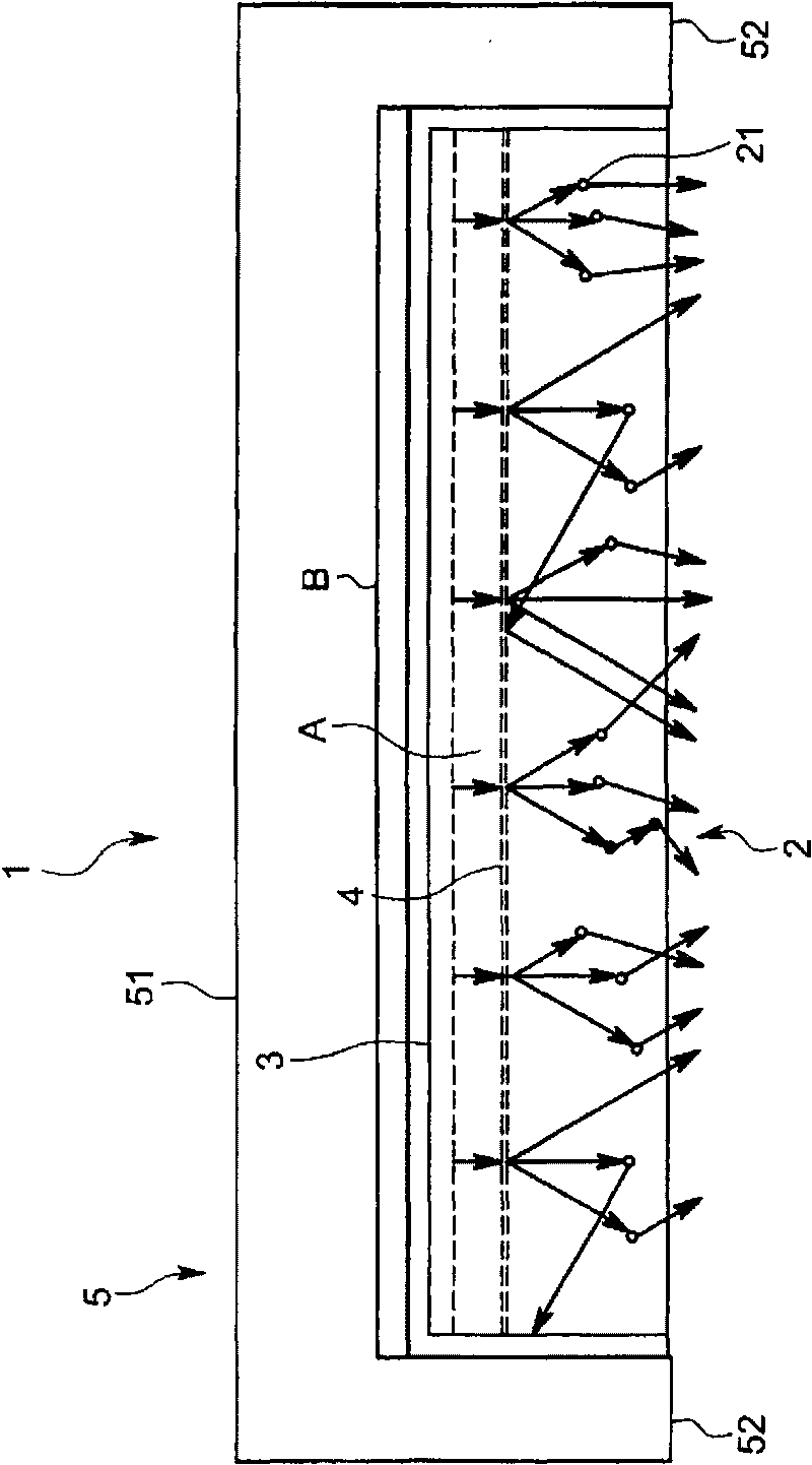
[0034] The LED lighting device 1 of this embodiment is used for general lighting such as indoor lighting instead of fluorescent lamps, for example, figure 1 As shown, it includes: a diffusion member 2; an LED3 mounted on the diffusion member 2; a light diffraction sheet 4 similarly installed on the diffusion member 2; holding these diffusion members 2, LED3 and light diffraction 4 holders 5 .

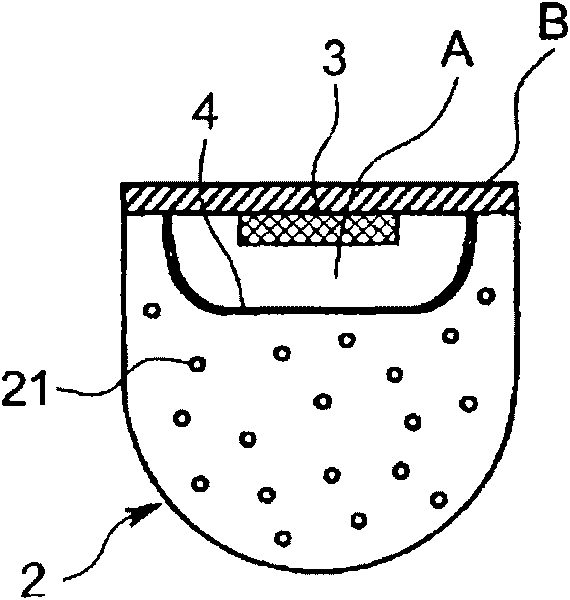
[0035] The diffusion member 2 is a transparent member made of resin, and includes light scattering particles 21 for diffusing light therein. The shape of the diffusion member 2, such as figure 1 and figure 2 As shown, it is a columnar shape with a cross section of approximately semicircle. In this embodiment, the groove A extending in the longitudinal direction is provided on the chord side of the substantially semicircular shape in the cross-sectional view of the diffusion me...


PUM


Abstract

An LED (3) is equipped with a thin-plate-shaped semiconductor element body (31) transmitting the light generated in a p-n junction region (34) in a thickness direction and emits it from the surface, a surface electrode (32) that is provided in such a manner as to cover the surface of the semiconductor element body (31), and a plurality of columnar dielectric antennas (36) penetrating through the surface electrode (32) in the thickness direction and condensing the light that is transmitted in the semiconductor element (31) body to emit it outside. There provided is an LED illuminator (1) provided with the LED (3), a diffraction member (4) that is arranged on the light emitting surface side of the LED (3) to diffract and disperse the light that is emitted by the LED (3), and a diffusion member (2) that is arranged outside the diffraction member (4) to diffuse the light that is dispersed by the diffraction member (4) and emits it outside. The LED illuminator (1) can substitute for a fluorescent light and can obtain uniform light with high efficiency.

Description

technical field [0001] The present invention relates to an LED lighting device using a high-efficiency LED capable of surface emission. Background technique [0002] Compared with fluorescent lamps and incandescent lamps, LEDs have a long life and stable light intensity, and there are few cases where it takes time to start up and causes problems in disposal. And recently, in addition to the development of LEDs that emit blue light and ultraviolet light, high-power LEDs have also been developed. LEDs are not only used in indicators as before, but are also being used in general lighting equipment. [0003] However, when compared in terms of total light quantity and illuminance, although the light quantity per unit light emitting area increases, LEDs are not as good as fluorescent lamps. In order to obtain the same amount of light as a fluorescent lamp as a whole, a plurality of LEDs must be provided, which results in a very large amount of heat generated, and as shown in Pate...

Claims


Application Information

Patent Timeline
Patent Type & Authority Applications(China)
IPC IPC(8): F21V5/00H01L33/00H01L33/20H01L33/38H01L33/50
CPCF21K9/00H01L33/382H01L33/20F21K9/30G02B5/1809G02B5/02F21Y2103/003H01L33/508F21K9/20F21Y2103/10F21Y2115/10
Inventor 铃木文雄
Owner ABEL SYST
Why Eureka
Try Eureka