Energy-saving compressed air drying method and device special for compression heat regenerative pipelines

A drying method and compressed air technology, applied in separation methods, chemical instruments and methods, separation of dispersed particles, etc., can solve problems such as high frequency, consumption of finished gas, and short switching time

Inactive Publication Date: 2010-06-16
杭州博大净化设备有限公司
View PDF0 Cites 24 Cited by
  • Summary
  • Abstract
  • Description
  • Claims
  • Application Information

AI Technical Summary

Problems solved by technology

However, in the conventional control method of compressed air dryers commonly used at present, most of the adsorbent regeneration in the process uses part of the product gas for regeneration. For example, the switching time of the heatless regeneration ads...

Method used


Image

  • Energy-saving compressed air drying method and device special for compression heat regenerative pipelines
  • Energy-saving compressed air drying method and device special for compression heat regenerative pipelines
  • Energy-saving compressed air drying method and device special for compression heat regenerative pipelines

Examples


Embodiment Construction

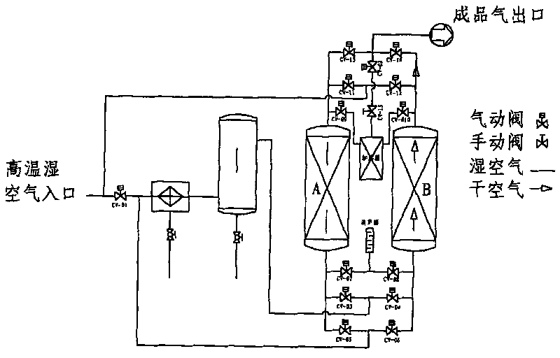
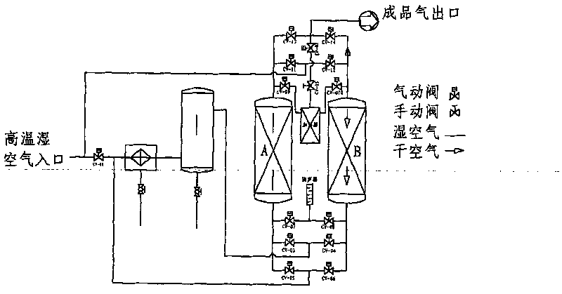
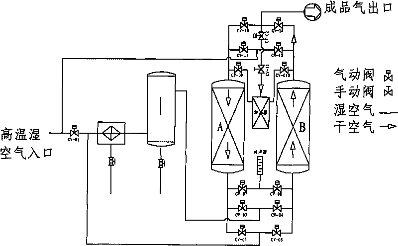
[0012] The present invention will be described in detail below in conjunction with the accompanying drawings: the special compressed air drying method for compressed heat regeneration type pipelines of the present invention includes at least one pair of adsorption towers that are mutually drying towers and regeneration towers, and is characterized in that The drying method includes the following two stages: one is drying - heating regeneration stage, the high temperature gas is sent to the regeneration tower first, then enters the air cooler to lower the temperature, and then flows into the gas-water separator to separate a small amount of interlaced liquid and then enters In the drying tower, the dried gas flows out for the user; the second is the drying-cold blowing regeneration stage, after the hot regeneration is completed, the PLC program controller issues an instruction, and the high-temperature gas changes direction under the control of the valve, and first flows into the...


PUM


Abstract

The invention discloses an energy-saving compressed air drying method and an energy-saving compressed air drying device special for compression heat regenerative pipelines. The method comprises the following two stages: a drying-heating regeneration stage, wherein high temperature gas is delivered to a regenerator, enters an air cooler for temperature reduction, flows into a gas-water separator and then enters a drying tower; and a drying-cold blowing regeneration stage, wherein the high temperature gas is controlled by a valve to change the direction, flows into the air cooler and the gas-water separator and then directly enters the drying tower for drying, wherein partial dried air taken from an outlet of the drying tower enters the regenerator for cold blowing regeneration. The device comprises a pair of adsorption towers which are formed by connecting a plurality of control valves and pipelines and is a drying tower and a regenerator mutually; the control valves are connected with a PLC program controller; a pipeline for delivering high temperature air is connected in parallel with a dry air supply pipeline formed by connecting the air cooler and the gas-water separator in series; and the front end of the dry air supply pipeline is connected with an outlet of a regenerative gas pipeline of the regenerator through a control valve. The energy-saving compressed air drying method and the energy-saving compressed air drying device avoid the defects of short switching time, high frequency and high gas consumption for generation of a heatless regenerative adsorption type drier, also overcome the defect that a heat regenerative adsorption type drier needs a heater to consume much electric energy, and ensure continuous production of high-quality gas and energy conservation.

Description

technical field [0001] The invention relates to a special compressed air drying method and device, belonging to an adsorption drying method and device. technical background [0002] With the rapid development of purification technology and the widespread application of adsorption dryers, the comprehensive energy consumption per unit production of product gas has become an important parameter to evaluate the performance of finished products. While ensuring the quality of product gas is stable, minimizing equipment energy consumption has become a major goal of purification. The direction of technology development and the pursuit of goals. From the principles of purification technology and practical experience, the main factors affecting the performance of finished products and unit energy consumption are the dynamic adsorption capacity of the adsorbent, regeneration efficiency, equipment structure and pipeline design, and equipment load. The dynamic adsorption capacity of the...

Claims


Application Information

Patent Timeline
IPC IPC(8): B01D53/26B01D53/04
Inventor 彭正惠
Owner 杭州博大净化设备有限公司
Why Eureka
Try Eureka