Automatic in-mould edge gate cutting injection mould

A technology for automatic cutting and injection molding, which is applied to the field of automatic cutting of injection molds and plastic injection molds at the inner gate of the mold. , the effect of prolonging the service life and reducing the manufacturing cost

Active Publication Date: 2010-06-16
DONGMING XINGYE SCI TECH CO LTD
View PDF2 Cites 31 Cited by
  • Summary
  • Abstract
  • Description
  • Claims
  • Application Information

AI Technical Summary

Problems solved by technology

[0008] 1. When the cutter cuts off the nozzle, its blade must touch the fixed mold, which requires the length of the cutter, the depth of the groove, the thickness of the lower inner ejector plate and the position and height of the lower surface of the fixed mold to be very accurate, otherwise it will It will cause continuous cutting, or the collision between the cutter and the lower surface of the fixed mold will cause damage to the mold and cutter
[0009] 2. During the entire mold opening process, the ejector rod is required to move twice, the first ejec

Method used


Image

  • Automatic in-mould edge gate cutting injection mould
  • Automatic in-mould edge gate cutting injection mould
  • Automatic in-mould edge gate cutting injection mould

Examples


Embodiment 1

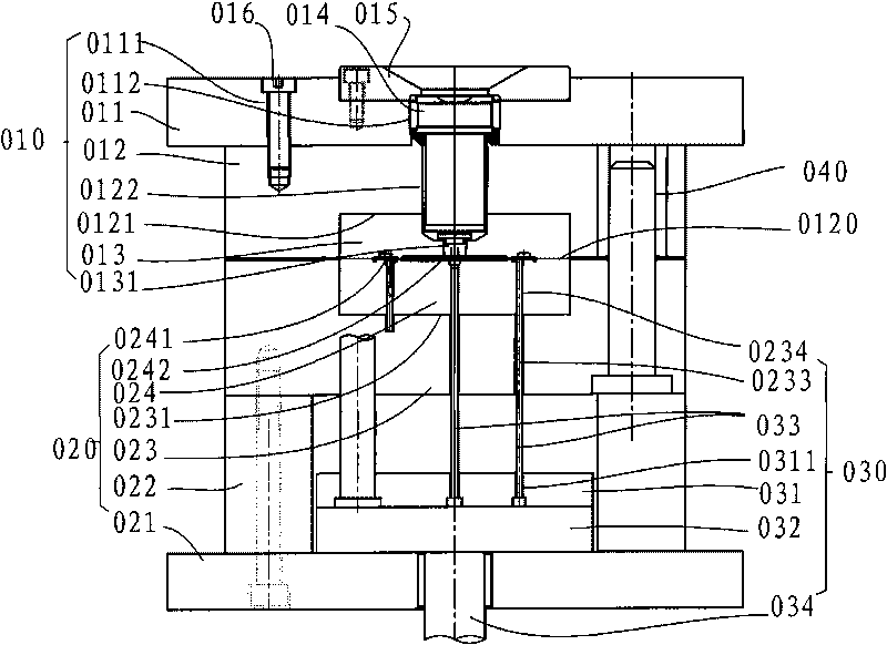
[0046] see image 3 A kind of mold inner side gate automatic cut-off injection mold of preferred embodiment of the present invention, comprises the fixed mold 10 that is made of fixed mold fixed plate 11, fixed template 12, fixed mold core 13, is made of movable mold fixed plate 21, pad iron 22. The movable mold 20 composed of the movable template 23 and the movable mold core 24, the ejector mechanism 30 composed of the upper ejector plate 31, the lower ejector plate 32, a plurality of ejector pins 33 and the ejector rod 34 of the injection molding machine, The guide post 41 and the guide sleeve 42 connecting the movable mold 20 and the fixed mold 30, and the gate cutting device 60, wherein the gate cutting device 60 includes a gate located at the side gate of the injection molded part, which passes through the fixed mold core 13 and the fixed template 12 A plurality of reset rod sliding holes 61, opposite to the plurality of reset rod sliding holes 61, a plurality of cutter s...

Embodiment 2

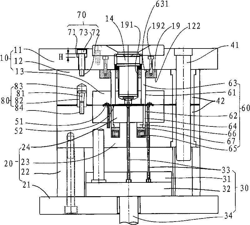
[0052] see Figure 4 Shown is another preferred embodiment of the injection mold with automatic cut-off of the gate inside the mold of the present invention, including a fixed mold composed of a fixed mold fixed plate 11', a fixed mold plate 12', and a fixed mold core 13' fixed sequentially. , the movable mold composed of the movable mold fixed plate 21, the pad iron 22, the movable template 23' and the movable mold core 24', the ejector formed by the upper ejector plate 31, the lower ejector plate 32 and a plurality of ejector pins 33 Mechanism, a guide post 41 and a guide sleeve 42 connecting the movable mold and the fixed mold, and a gate cutting device, wherein the gate cutting device includes a gate located at the side gate of the injection molded part, passing through the movable mold core 24' and the movable template 23' A plurality of reset rod sliding holes 61', opposite to the plurality of reset rod sliding holes 61', a plurality of cutter sliding holes 62' passing t...


PUM


Abstract

The invention relates to a plastic injection mould, in particular to an automatic in-mould edge gate cutting injection mould comprising a fixed mould, a movable mould, an ejecting mechanism, a guide post and a guide bush which are used for connecting the movable mould and the fixed mould, and a gate cutting device, wherein the gate cutting device comprises a plurality of resetting rod slide holes positioned on an edge gate of an injection part and penetrating a fixed mould core and a fixed mould plate, and a plurality of cutter slide holes penetrating a movable mould core, resetting rods are arranged in the resetting rod slide holes, and cutters are arranged in the cutter slide holes; the cutters abut against the end faces of the resetting rods which are fixed with a fixing plate of the fixed mould; the cutters abut against a movable mould plate through springs; a separation inhibiting device is arranged between the fixed mould plate and the fixing plate of the fixed mould, and a mould separating damper is arranged between the fixed mould plate and the movable mould plate. The mould opening force of an injection machine is used for cutting off a gate runner in the process of mould opening; and concretely, the cutters do shearing movements opposite to the edge gate of the part through the spring force at the bottoms of the cutters to automatically shear and separate the injection part and the gate, and therefore, the automatic in-mould edge gate cutting injection mould dispenses with the subsequent process of cutting off the gate.

Description

technical field [0001] The invention relates to a plastic injection mold, which belongs to the field of moulds, in particular to an injection mold with automatic cut-off gate inside the mold. It is to install a shearing device in the mold. During the mold opening process, the gate runner is cut off by using the mold opening force of the injection molding machine. Specifically, the spring force at the bottom of the cutter makes the cutter move against the side gate of the part. Shearing motion automatically shears and separates the injection molded part from the gate, eliminating the need for subsequent gate removal. Background technique [0002] The current plastic injection mold in the form of side gate glue injection is as follows: figure 1 As shown, it mainly includes a fixed mold 010 , a movable mold 020 and an ejection mechanism 030 , and a parting surface 0120 , a cavity 0241 and a runner 0242 are formed between the fixed mold 010 and the movable mold 020 . The fixed...

Claims


Application Information

Patent Timeline
IPC IPC(8): B29C45/38B29C45/26
Inventor 王宏烈张建立肖红飞
Owner DONGMING XINGYE SCI TECH CO LTD
Why Eureka
Try Eureka