Device for detecting and separating impurity in or between fiber materials on spinning preparation machine

A technology for separating fibers and preparing machines, which is applied in the direction of analyzing materials, fiber processing, fiber feeding, etc. It can solve the problems of reducing separator efficiency, increasing air pressure, and complicated equipment, and achieves the effect of saving space, avoiding pollution, and compact structure

Active Publication Date: 2010-06-16
TRUETZSCHLER GRP SE
View PDF6 Cites 7 Cited by
  • Summary
  • Abstract
  • Description
  • Claims
  • Application Information

AI Technical Summary

Problems solved by technology

[0007] The second factor that reduces the efficiency of the separator is that the large number of valves and long hold times result in a large amount of air being sent to the waste chamber, which causes an increase in air pressure in the chamber and thus air backflow into the feed channel
The device is complex in ter

Method used


Image

  • Device for detecting and separating impurity in or between fiber materials on spinning preparation machine
  • Device for detecting and separating impurity in or between fiber materials on spinning preparation machine
  • Device for detecting and separating impurity in or between fiber materials on spinning preparation machine

Examples


Embodiment Construction

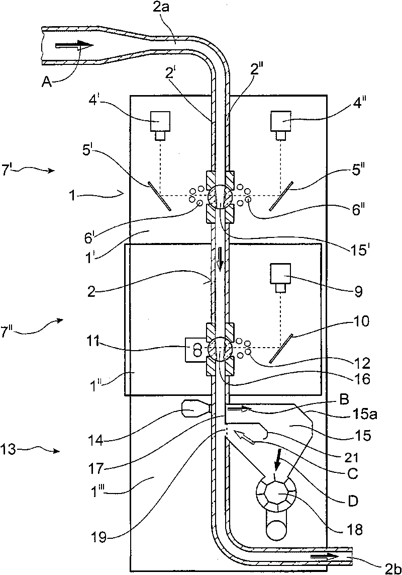
[0029] Such as figure 1 As shown, a vertical channel 2 is arranged inside the frame 1, and the parallel side walls 2', 2" opposite to each other are at least partially configured as transparent panels, and the outsides of the side walls 2', 2" are connected with lighting devices.

[0030] The first detection device 3 comprises two CCD cameras 4', 4" (line scan cameras), which act indirectly on the glass channel 15' via two mirrors 5' and 5" inclined at an angle, respectively. . The optical planes are arranged slightly offset from each other. On the side wall of the tunnel 2 opposite the camera 4' an illumination system 6'' is arranged, and on the side wall of the tunnel 2 opposite the camera 4'' an illumination system 6' is arranged. In this way, the material in the glass channel 15' is detected from both sides by the two cameras 4', 4".

[0031] The frame 1' containing the glass channel 15', the camera 4', 4", the tilting mirror 5', 5" and the lighting system 6', 6' consti...


PUM


Abstract

The present invention provides a device used for detecting and separating impurity in or between fiber materials on a spinning preparation machine (or a cotton gin or analog). The device is provided with a fiber transmission pipe. A sensor system for detecting the impurity and a separation device are sequentially provided along the pipe in the transmission direction. The separation device is provided with at least one compression air nozzle (for blowing air) which operates transversely with the fiber transmission pipe. The fiber transmission pipe is provided with a first opening opposite with the compression air nozzle. The first opening is introduced to a separation chamber connected with a waste discharge device. Furthermore the blowing air from at least one compression air nozzle can be supplied to the conveying air flow in a closed system from the separation chamber through an additional opening. For reliably insulating the impurity from the fiber material flow with a mode with simple structure and preventing generating negative influence for the air balance, the separation chamber is integrally connected with the fiber transmission pipe. Furthermore the blowing air passes through a filter, a sieve or analog before returning to the conveying air flow.

Description

Technical field: [0001] The present invention relates to a device for detecting and separating impurities in or between fibrous materials, especially cotton fibers, on a spinning preparation machine, a cotton gin or the like, the device having a fiber conveying duct along which in the direction of conveying A sensor system for detecting impurities and a separating device are arranged in succession above, the separating device having at least one compressed air nozzle (blow air) operating transversely to the fiber conveying duct, which has a first opening opposite the compressed air nozzle , the opening opens into a separation chamber connected to the waste removal device, and the blowing air from the at least one air nozzle can be resupplied in a closed system from the separation chamber through a further opening to the conveying air flow. Background technique: [0002] In practice, a key requirement for trash separators on spinning room preparation machines and similar equi...

Claims


Application Information

Patent Timeline
IPC IPC(8): D01G31/00
CPCD01G31/003D01G23/08G01N21/85G01N21/8915
Inventor G·恩格斯K·滕布格
Owner TRUETZSCHLER GRP SE
Why Eureka
Try Eureka