Wave weakening structure for bridge tower

A technology for bridge towers and wave elimination, applied in bridges, bridge parts, bridge construction, etc., can solve problems such as cumbersomeness, huge structure, and difficulty, and achieve the effects of low cost, wave force reduction, and simple structure.

Active Publication Date: 2011-10-05
CCCC HIGHWAY CONSULTANTS +1
View PDF0 Cites 2 Cited by
  • Summary
  • Abstract
  • Description
  • Claims
  • Application Information

AI Technical Summary

Problems solved by technology

[0006] The study found that the above-mentioned breakwater structure or wave dissipation principle of the wave dissipation block is worth learning, but there are certain difficulties in applying it directly to bridge towers for wave dissipation. The reasons are: (1) The breakwaters currently used in port and wharf engineering The main purpose is to reduce the wave reflectivity and reduce the wave energy exchange on the side of the port and wharf engineering facing the sea as much as possible. Therefore, the wave dissipation structure is often self-contained and placed directly on the seabed, and the structure is relatively large and cumbersome.

Method used


Image

  • Wave weakening structure for bridge tower
  • Wave weakening structure for bridge tower
  • Wave weakening structure for bridge tower

Examples


Embodiment Construction

[0026] Now in conjunction with accompanying drawing the present invention is described in further detail:

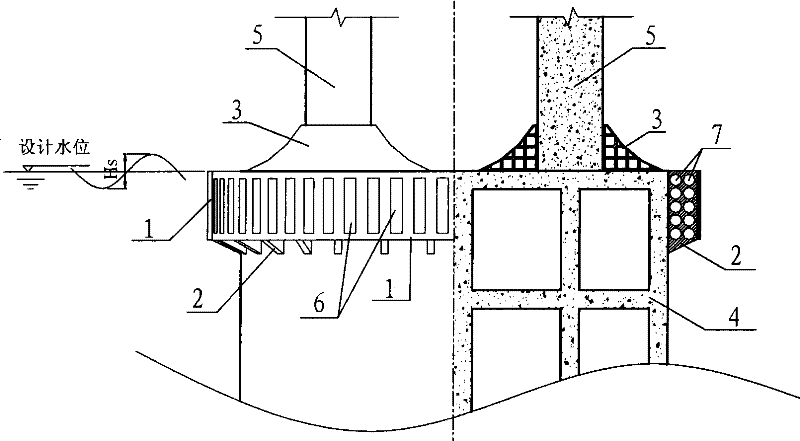
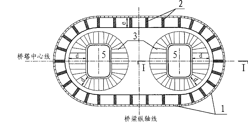
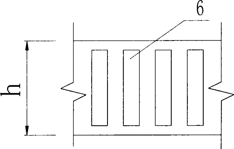
[0027] The invention is a wave dissipation structure for a bridge tower, which is composed of a sleeve 1, a support plate 2 and a wave guiding block 3 with a concave curved surface. The sleeve 1 is arranged around the bridge tower foundation 4 through the support plate 2, and is arranged in a ring on the plane (such as figure 1 , 2 shown); the height of the sleeve 1 is 1.5 to 2.0 times the design wave height, and is provided with a vertical rectangular through hole 6 (such as image 3 shown), the porosity is 30% to 50%. The sleeve 1 is fixed on the bridge foundation 4 through the support plate 2, the support plate 2 is trapezoidal, and the bottom is h 1 , the top edge is h 2 , the height is f, where: h 2 =h, f=e (as Figure 4 shown). Open round through hole 7 on support plate 2 (as Figure 4 shown), the opening ratio is 40% to 60%, and these through holes can ens...


PUM


Abstract

The invention provides a wave weakening structure for a bridge tower, which relates to a bridge technology and comprises a sleeve barrel, a supporting plate and a wave guiding block, wherein the top surface of the foundation of the bridge tower is flush with the design water level; the flaky supporting plate is vertically and fixedly arranged on the side circumferential surface of the foundation;circular through holes are formed on the supporting plate, and the aperture ratio is 40%-60%; the bottom surface of the wave guiding block with a horn-shaped concave curved surface is fixedly connected with the top surface of the foundation, and the inner side surface is fixedly connected with the tower column of the bridge tower; the outer end of the supporting plate is fixedly connected with the annular sleeve barrel; the top end of the sleeve barrel is flush with the top surface of the foundation; vertical strip-shaped through holes are formed on the sleeve barrel, and the aperture ratio is 30%-50%; the height of the wave guiding block and the sleeve barrel is 1.5-2.0 times of the design wave height; the sleeve barrel, the supporting plate and the foundation of the bridge tower together form an annular wave weakening chamber; the thickness of the annular wave weakening chamber is 1 / 10-1 / 5 time of the design wavelength, and the top and the bottom of the annular wave weakening chamber are open; and the sleeve barrel, the supporting plate and the wave guiding block are made of steel products or reinforced concrete or composite materials. The wave weakening structure of the invention consumes and absorbs the wave energy, effectively weakens the effect of the wave force on the bridge tower, and has the advantages of simple structure, convenient installation and good economic benefit.

Description

technical field [0001] The invention relates to the technical field of bridge engineering, and relates to an auxiliary structure of a bridge tower, which is used to reduce the wave force acting on the bridge tower. Background technique [0002] The environment of the bridge towers of cross-sea bridges is relatively harsh, and waves have an impact on the bridge towers. This impact is a random dynamic load with a large peak value, which will pose a serious threat to the bridge. In order to ensure the safety of the bridge structure, it is necessary to develop a special wave dissipation structure to reduce the wave force acting on the bridge tower according to the characteristics and functional requirements of the bridge tower structure. [0003] According to engineering practice and experimental research, for powerful destructive waves, the method of reducing wave energy or following the waves is more effective than the method of direct resistance. Therefore, countries all ove...

Claims


Application Information

Patent Timeline
Patent Type & Authority Patents(China)
IPC IPC(8): E01D19/02
Inventor 刘高刘天成张喜刚徐国平王秀伟陈上有吴宏波李毅
Owner CCCC HIGHWAY CONSULTANTS
Why Eureka
Try Eureka