Trapezoidal-block embankment structure

A trapezoidal block and embankment technology, applied in the field of embankment structure of embankments, can solve the problems of limited ability to resist wave action, large amount of concrete, and insufficient ability to resist wave action.

Inactive Publication Date: 2014-05-07
SHANGHAI WATERWAY ENG DESIGN & CONSULTING
View PDF5 Cites 3 Cited by
  • Summary
  • Abstract
  • Description
  • Claims
  • Application Information

AI Technical Summary

Problems solved by technology

Its disadvantages are: similar to block stones, it is composed of many prefabricated concrete blocks stacked vertically, which is a loose structure, and its ability to resist wave action is limited. The embankment width should not be less than 3 times the design wave height value, and the amount of concrete is large
Its disadvantages are as follows: 1) The main body in front of the wall is still a straight wall, and the standing wave effect is significant (the code still considers the wave pressure according to the standing wave), and the wave force is large; 2) The resultant force of the wave force points outside the rear toe of the vertical embankment, which is against the tilting of the vertical embankment. Stability is unfavorable; 3) When the height of the embankment is high, the average base pressure caused by the self-weight basically increases linearly, and the base pressure caused by the wave action forms a trapezoidal distribution. After the superposition of the two, the local base pressure further increases. It cannot be used on soil foundations, and a thicker riprap bed is also required on foundations with medium bearing capacity
[0005] 3. Horizontal mixed vertical embankment: the back wave side is an upright embankment, and the front wave side is filled with many artificial blocks to form a slope. Insufficient to caisson vertical embankment
Its disadvantages are as follows: 1) Although the semicircular member is provided with a pressure relief hole on the bottom plate to reduce the wave buoyancy force, its width is basically twice the height. Since the weight and height are basically square, and it is a hollow structure, when When used in conditions of high foundation bed, short embankment, and large waves, due to height restrictions and hollow effects, the weight of the semicircular member is small, and the ability to resist wave action often cannot meet the needs; 2) Although the semicircular caisson has fillers and self-weight increase, but the width is basically twice the height. Since the weight and height are basically in a square relationship, when used in conditions of high foundation bed, short embankment, and large waves, the weight of the semicircular caisson is limited by the height, and it cannot If pressure relief holes are installed, the wave pressure and wave buoyancy cannot be reduced, and the ability to resist wave action often cannot meet the stability requirements; Punching ability) is poor, resulting in frequent accidental damage to ships and other drifting objects
However, this technology has the following deficiencies: 1) Since the weight of the triangular caisson has a square relationship with the height, when it is used in conditions of high foundation bed, short embankment, and large waves, the weight of the triangular caisson is limited by the height, and the ability to resist waves is often It cannot meet the stability requirements; 2) The side plate of the caisson is a thin-walled structure, which has poor resistance to concentrated force (punching ability), and is easily damaged if it is accidentally hit by drifting objects such as ships; It is easy to be damaged by accidental impact of drifting objects

Method used


Image

  • Trapezoidal-block embankment structure
  • Trapezoidal-block embankment structure
  • Trapezoidal-block embankment structure

Examples


Embodiment 1

[0059] Embodiment 1: A trapezoidal block embankment structure (without wave dissipation and pressure relief holes) is placed on the built slope embankment to form a guide embankment.

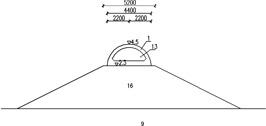
[0060] 1) The design conditions of a certain guide embankment are: the existing slope embankment 16 is a throw-filled large rock structure, the minimum particle size of the rock is 0.6m, the top elevation is 2.3m, and the top width is 5.2m. It is necessary to increase the elevation of the dike crest to 4.5m on the basis of the existing slope embankment 16, the elevation of the beach surface in front of the embankment is -2m, the design low water level is 0.08m, the design high water level is 4.11m, and the wave H 1% =3.5m, T=7.6s, L=58m.

[0061] 2) If prior art semicircular caissons are placed on the built slope embankment 16 to form a guide embankment, see figure 1 , figure 2 , prefabricated and placed a semicircular caisson 1 on the top of the existing slope embankment 16 (as a foundation...

Embodiment 2

[0076] Embodiment 2: A trapezoidal block embankment structure (wave dissipation and pressure relief holes connecting up and down) is placed on the built slope embankment to form a guide embankment.

[0077] The design conditions of a guide embankment are: the existing slope embankment 16 is a throw-filled large rock structure, the minimum particle size of the rock is 0.6m, the top elevation is 2.3m, and the top width is 5.2m. It is necessary to increase the elevation of the dike crest to 4.5m on the basis of the existing slope embankment 16, the elevation of the beach surface in front of the embankment is -2m, the design low water level is 0.08m, the design high water level is 4.11m, and the wave H 1% =3.5m, T=7.6s, L=58m.

[0078] see Figure 15 , Figure 16 , on the top of the existing slope embankment 16 (as the foundation bed), the trapezoidal blocks 3 with a cross-sectional direction of a whole block are placed longitudinally and continuously one by one, arranged and con...

Embodiment 3

[0082] Embodiment 3: Trapezoidal block embankment structure (without wave dissipation and pressure relief holes).

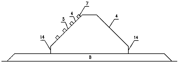
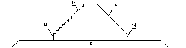
[0083] see Figure 12 , Figure 13 , Figure 14 , trapezoidal block embankment structure (without wave-dissipating and pressure-relief holes), which is formed by placing trapezoidal blocks 3 in the cross-sectional direction as a whole on the riprap foundation bed 8, and connecting them one by one in the longitudinal direction. The trapezoidal blocks 3 It is a block whose cross-sectional direction is approximately trapezoidal, and the overall shape is approximately trapezoidal prism, and the angle between the slope surface 4 on both sides of the trapezoidal block and the horizontal plane is not greater than 60°. The connection method of longitudinally adjacent trapezoidal blocks 3 is vertical plane contact connection, or vertical tongue-and-groove tenon joint, the seam width is generally not greater than 5cm, or vertical plane plus rubber water-stop contact conn...


PUM


Abstract

The invention discloses a trapezoidal-block embankment structure and relates to an embankment structure of embankment engineering. In the technical scheme, the embankment structure is formed by arranging trapezoidal blocks with a complete block in the cross-section direction on a foundation bed and carrying out longitudinal and continuous arrangement and connection on the blocks gradually; each trapezoidal block is a block body with the cross-section direction being similar to trapezoid and the whole body being similar to a trapezoidal prism; the included angles between the slope surfaces of the two horizontal sides of each trapezoidal block and the horizontal plane are not larger than 60 degrees, and are larger than or equal to 18 degrees and smaller than or equal to 45 degrees when waves are larger; the height of straight walls at the two horizontal sides of each trapezoidal block is not more than 1/3 of the height of each trapezoidal block; wave-absorbing and pressure-releasing holes can be arranged on the slope surface of each trapezoidal block. The trapezoidal-block embankment structure disclosed by the invention has the technical effects that the foundation pressure is less, the stability against overturning and the stability against the sliding in waves are good, and the capability for resisting accidental impact of floating objects such as ships is strong. The trapezoidal-block embankment structure is applicable to improving embankment structures, wave-wall structures and breast-wall structures of dam engineering such as buildings, breakwaters, sand control dams and revetments in the field of dam engineering.

Description

technical field [0001] The invention belongs to the field of dyke engineering and relates to a dyke body structure. Background technique [0002] According to technical documents such as "Code for Design and Construction of Breakwaters" (JTS 154-1-2011), the background technology of embankment structures such as remediation buildings, breakwaters, sand dikes, revetments, etc. that are closer to the present invention are as follows: [0003] 1. Throwing and filling block slope embankment: Prefabricated concrete blocks are used to replace block stones, and the trapezoidal section is thrown and filled without face protection. Its disadvantages are: similar to block stones, it is composed of many prefabricated concrete blocks stacked vertically, which is a loose structure, and its ability to resist wave action is limited. The embankment width should not be less than 3 times the design wave height, and the amount of concrete will be large. [0004] 2. Chamfered caisson vertical...

Claims


Application Information

Patent Timeline
Patent Type & Authority Applications(China)
IPC IPC(8): E02B3/04E02B3/06
CPCY02A10/11
Inventor 马兴华周海陈张忱殷昕陈琳季岚王费新
Owner SHANGHAI WATERWAY ENG DESIGN & CONSULTING
Why Eureka
Try Eureka