Temperature controller of engine

A temperature controller and engine technology, applied in the direction of engine components, machine/engine, engine cooling, etc., can solve problems such as failure to reach, defective structure, etc., and achieve the effects of reasonable structure design, sufficient combustion, and accurate regulation

Inactive Publication Date: 2010-06-16
梁国胜
View PDF3 Cites 12 Cited by
  • Summary
  • Abstract
  • Description
  • Claims
  • Application Information

AI Technical Summary

Problems solved by technology

[0008] The purpose of the present invention is to provide an improved engine temperature controller, which solves the problem that the existing structure of adjusting the working temperature of the engine cannot meet the ideal requirements in the prior art. The engine is always kept at the best working temperature in any climate environment, which significantly improves the engine's operating performance, thereby reducing fuel consumption, reducing harmful gas emissions, fully improving the engine's ability to output power, and prolonging the service life of the engine

Method used


Image

  • Temperature controller of engine
  • Temperature controller of engine
  • Temperature controller of engine

Examples


Embodiment Construction

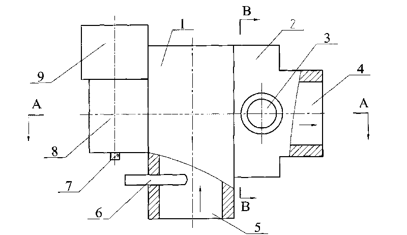
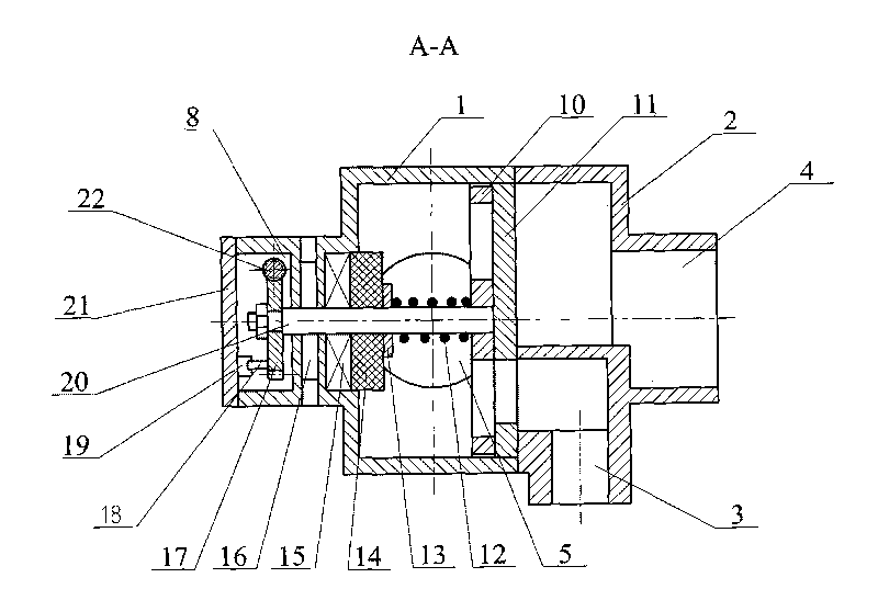
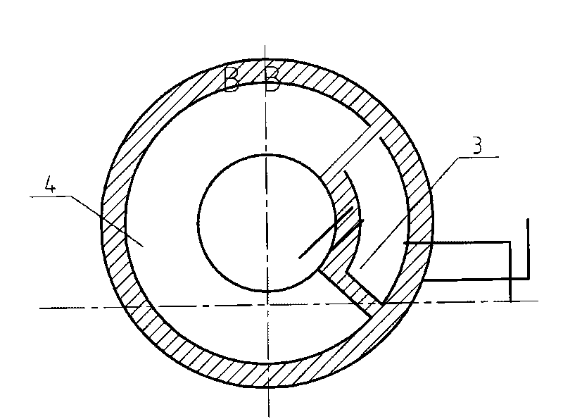
[0031] according to Figure 1-12 The specific structure of the present invention will be described in detail. The engine thermostat includes a valve body respectively provided with a coolant inlet 5 and coolant large and small circulation outlets 4, 3, and a worm gear shaft 20 driven by a stepping motor 9 driven by a speed reducer 8 assembled on the valve body. The shaft 20 is directly or indirectly driven to control the temperature control actuator of the large and small circulation loops of the coolant, and the mature technology automatic control loop mainly composed of the microcomputer control mechanism 35 for the large and small circulation loops of the coolant. Wherein the stepper motor 9 and the speed reducer 8 made of worm gear and worm screw all adopt common structures. In order to facilitate installation and maintenance, a speed reducer end cover 21 is set at the end of the speed reducer 8 casing. In order to cut off the leakage of coolant and steam from the inner c...


PUM


Abstract

The invention relates to an improved temperature controller of an engine, which can solve the problems that the structure for regulating and controlling the working temperature of the engine in the prior art is poor and can not achieve the ideal requirements. The temperature controller comprises a valve body, a worm gear shaft assembled on the valve body, a temperature control actuating mechanism for controlling a large circulation loop and a small circulation loop of coolant and an automatic control loop for the large circulation loop and the small circulation loop of the coolant, and the automatic control loop mainly consists of a micro-computer control mechanism. The technical key points are as follows: the I type temperature control actuating mechanism is directly driven by utilizing the worm gear shaft, or the II type temperature control actuating mechanism is driven by utilizing the worm gear shaft and a rack shaft which is arranged on the worm gear shaft and meshed with a gear, thereby controlling the large circulation loop and the small circulation loop of the coolant respectively. The structural design is reasonable, and the regulation and the control are accurate and reliable, thereby always keeping the engine at the optimal working temperature state when running under any climate and environment, obviously improving the running performance of the engine, further reducing the fuel consumption, reducing the harmful gas emissions, fully improving the capability of outputting the power of the engine and prolonging the service life of the engine.

Description

technical field [0001] The invention relates to a control device for improving the operating temperature of an engine, in particular to an engine temperature controller for keeping the engine running at the optimum operating temperature, reducing fuel consumption, reducing harmful gas emissions, and prolonging service life, which belongs to the engine supporting part. Background technique [0002] As we all know, the engine can only exert its maximum working efficiency under the condition of maintaining the optimal working temperature (generally 85°C-95°C). Therefore, most of the engines work under the condition of temperature adjustment, trying to forcefully control the circulating water cooling system. To maintain the optimum working temperature. However, when the ambient temperature is too high or too low, it is difficult for this method to control the working temperature and keep it in the optimum temperature range. Common temperature adjustment methods, that is, the m...

Claims


Application Information

Patent Timeline
Patent Type & Authority Applications(China)
IPC IPC(8): F01P7/16
CPCF01P7/167
Inventor 梁国胜梁效
Owner 梁国胜
Why Eureka
Try Eureka