Driving limited-slip differential

A limited-slip differential, limited-slip technology, applied in differential transmission, transmission, belt/chain/gear, etc. problems, to achieve the effect of improving driving stability and safety, ensuring steering flexibility and stability, and easy electronic control

Inactive Publication Date: 2012-06-27
ZHEJIANG SCI-TECH UNIV
View PDF0 Cites 0 Cited by
  • Summary
  • Abstract
  • Description
  • Claims
  • Application Information

AI Technical Summary

Problems solved by technology

But the disadvantage of this ordinary differential is that the differential speed is not bad. If the friction inside the differential is ignored, the driving force of the driving wheels on the left and right sides is equal. When the adhesion coefficients of the wheels on both sides are inconsistent with the ground, The driving force of the vehicle is limited by the side of the road surface with a small adhesion coefficient. It often happens that the wheels on one side spin in situ while the wheels on the other side stop. The lateral adhesion of the ground decreases, the drive shaft slips laterally, and the vehicle slips out of control, causing serious accidents
At present, most vehicles with advanced technology adopt traction control system (TCS) or vehicle anti-skid control system (ASR). ASR prevents slippage during wheel driving by taking appropriate brakes on the slipping wheels, but these methods reduce the driving force of the wheels, and the vehicle may not be able to move forward
Some large trucks and construction machinery install a differential lock on the differential. If necessary, the differential is locked to allow the drive wheels on both sides to rotate at the same speed, which improves the driving ability of the vehicle. The fully self-locking mechanical differential The brake needs to be manually operated in the parking state. Once you forget to release the self-locking, it will increase driving resistance, increase fuel consumption, and cause serious tire wear.
In recent years, friction plate limited-slip differentials and jaw-type limited-slip differentials have also appeared. The former adds limited-slip friction pairs inside the differential. When the wheels on both sides slip, the friction pairs are compressed. Generate friction to prevent slipping, and transfer part of the driving force of the wheel on the slipping side to the non-slipping wheel on the other side, thereby improving the driving force of the vehicle, but when the vehicle is turning normally, the limit of the friction pair The sliding effect still occurs, which is not conducive to the turning of the vehicle, and the differential cannot control the locking coefficient according to the road surface conditions
The latter is that when the wheels on both sides slip, the wheel on the faster side floats, and the driving force of the whole vehicle is completely borne by the wheel on the other side, which makes the total driving force not limited by the slipping wheels. The driving force is improved, but when the vehicle is turning normally, the wheel on the faster side is also disengaged from the transmission, and the total driving force decreases, which cannot be fully suitable for various working conditions of the vehicle, and the structure is complex, the precision is high, and the noise is large
The above two differentials have some applications in automobiles and construction machinery, but the number is not large, and their technologies are imported from abroad, and the domestically developed products are still in the research stage

Method used


Image

  • Driving limited-slip differential
  • Driving limited-slip differential
  • Driving limited-slip differential

Examples


Embodiment Construction

[0026] The present invention will be further described below in conjunction with drawings and embodiments.

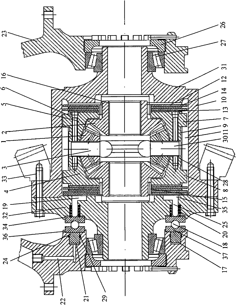
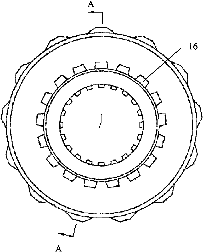
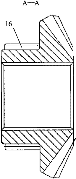
[0027] Such as figure 1 As shown, the differential gear of the present invention is made up of planetary gear train, limited-slip friction pair, outer casing, inner casing and hydraulic thrust mechanism etc. Among them, the planetary gear train is composed of planetary gear 1, side gear 2 and cross shaft 3. The four planetary gears 1 are installed on the four shafts of the cross shaft 3, and the two side gears 3 are placed on both sides of the cross shaft 3 and meshed with the four planetary gears 1 to form a planetary gear train, which is placed inside Inside the casing, a differential mechanism is formed. Such as figure 1 As shown, the inner shell is composed of the left half shell 4 and the right half shell 5, the cross shaft 3, the left half shell 4 and the right half shell 5 of the inner shell are fixedly connected into one body through the inner shell bolt 6, a...


PUM


Abstract

The invention discloses a driving limited-slip differential, comprising an outer shell, an inner shell, a planetary gear train, a limited-slip friction pair and a hydraulic pressure thrust mechanism, wherein, the joint cross of the planetary gear train is placed in a cross round groove of a left semi-shell and a right semi-shell of an inner shell and is fixedly connected with the left semi-shell and the right semi-shell; a first cavity which is matched with a compression ring of the hydraulic pressure thrust mechanism and a seat ring of a thrust bearing is arranged in the outer shell; the compression ring is arranged in the first cavity; a lateral end face of the compression ring is adjacent to the limited-slip friction pair; a push rod is arranged on the other lateral end face; a return spring is sheathed on the push rod; the poppet of the differential is internally provided with an oil duct and a secondary cavity which is matched with a circular ring hydraulic cylinder of the hydraulic pressure thrust mechanism and the seat ring of the thrust bearing; the circular ring hydraulic cylinder is arranged in the second cavity; the two seat rings of the thrust bearing are respectively placed in the first cavity and the second cavity; the seat ring of the first cavity and the return spring are tightly contacted with the head part of the push rod; the seat ring of the second cavity is tightly contacted with the piston of the circular ring hydraulic cylinder; and the oil duct is communicated with the cylinder body of the circular ring hydraulic cylinder.

Description

technical field [0001] The invention relates to a driving limited-slip differential, which is mainly used in automobiles, agricultural transport vehicles, wheeled engineering machinery and other wheeled machinery, and belongs to the fields of mechanical engineering and vehicle engineering. Background technique [0002] The differential of the vehicle drive axle is an important part of the vehicle power transmission system. The ordinary differential is mainly composed of planetary gears, cross shafts, half shaft gears and housings. The function of the differential is to realize the differential speed when the wheel speeds on both sides of the drive shaft are inconsistent (such as when the vehicle is turning), so as to avoid wheel slippage and reduce driving resistance and tire wear. But the disadvantage of this ordinary differential is that the differential speed is not bad. If the friction inside the differential is ignored, the driving force of the driving wheels on the lef...

Claims


Application Information

Patent Timeline
Patent Type & Authority Patents(China)
IPC IPC(8): F16H48/32F16H48/22F16H48/06F16H48/27
Inventor 吴跃成夏云清季小伟谢佩
Owner ZHEJIANG SCI-TECH UNIV
Why Eureka
Try Eureka