Light-emitting module and illumination device

A technology of light-emitting modules and light-emitting diodes, applied in lighting devices, fixed lighting devices, lighting auxiliary devices, etc., to achieve the effects of suppressing temperature rise, good thermal conductivity, and preventing glare or bright spots

Inactive Publication Date: 2010-06-16
TOSHIBA LIGHTING & TECH CORP
View PDF3 Cites 9 Cited by
  • Summary
  • Abstract
  • Description
  • Claims
  • Application Information

AI Technical Summary

Problems solved by technology

[0009] The object of the present invention is to overcome the defects of existing light-emitting modules and lighting devices, and provide a light-emitting module and lighting device with a new structure. The increase in chip temperature and the cost are also advantageous, making it more suitable for practical use

Method used


Image

  • Light-emitting module and illumination device
  • Light-emitting module and illumination device
  • Light-emitting module and illumination device

Examples


Embodiment Construction

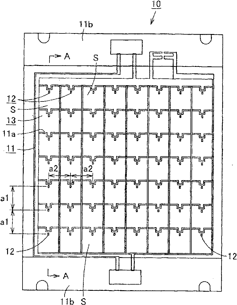
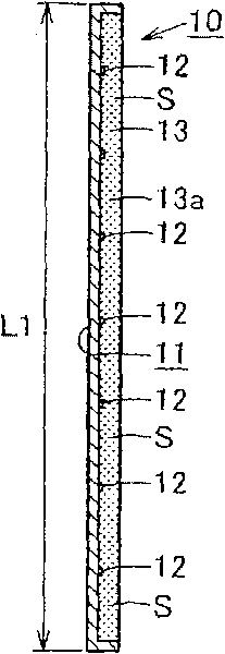
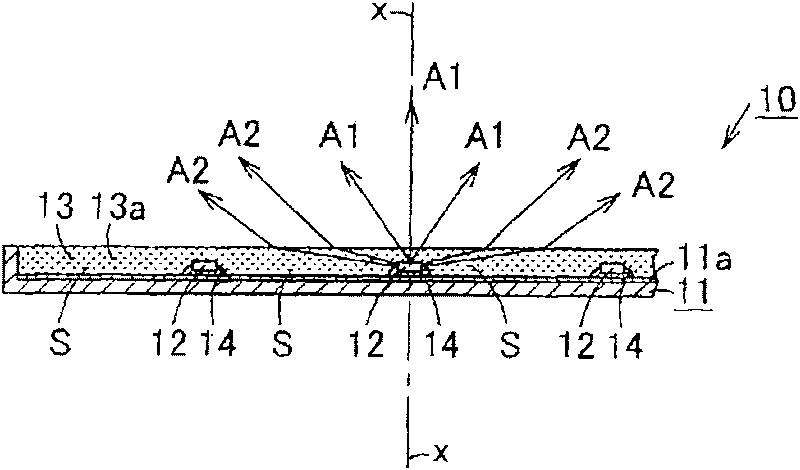
[0063] In order to further explain the technical means and effects of the present invention to achieve the intended purpose of the invention, the specific implementation of the light-emitting module proposed according to the present invention and the lighting device using the light-emitting module will be described below in conjunction with the accompanying drawings and preferred embodiments. , structure, feature and effect thereof, detailed description is as follows.

[0064] The aforementioned and other technical contents, features and effects of the present invention will be clearly presented in the following detailed description of preferred embodiments with reference to the drawings. Through the description of the specific implementation mode, a more in-depth and specific understanding of the technical means and effects adopted by the present invention to achieve the intended purpose can be obtained. However, the accompanying drawings are only for reference and description...


PUM


Abstract

There is provided a light-emitting module which makes it difficult to sense glare and which suppresses the temperature rise of light-emitting diode chips and has a cost advantage. The light-emitting module is provided with a base body (11) formed with a non-metallic member having a thermal conductivity of 1 W / mk or less. In the base body, a plurality of LED chips (12) are spaced 10 to 30 mm apart from each other, and their junction temperature when they are normally lit is preferably set at 90 DEG C or less. A translucent sealing member (13) covering an area between the adjacent light-emitting diode chips (12) is provided.

Description

technical field [0001] The invention relates to a light-emitting diode (Light-emitting diode) as a light source (light module) and a lighting device. Background technique [0002] In recent years, light-emitting diodes have been used as light sources of large lighting devices used in offices, general lighting, etc. due to their improved luminous efficiency, and have been gradually commercialized. In this lighting device, a chip on board (COB) module capable of densely arranging a plurality of light emitting diodes is often used. [0003] For example, there is a ceiling direct-mounted lighting device or a suspended lighting device in which a plurality of light-emitting diodes are arranged in a matrix on a substantially planar substrate to form a light-emitting module (COB). module), and use the light emitting module as a light source (for example, refer to Japanese Patent Laid-Open No. 2004-95655). In addition, there is a lighting device in which a plurality of light-emitti...

Claims


Application Information

Patent Timeline
Patent Type & Authority Applications(China)
IPC IPC(8): F21S8/00F21V19/00F21V5/00F21V7/00F21V15/02F21V23/00F21Y101/02
CPCH01L2924/0002F21Y2101/02F21V21/30H01L33/54F21K9/00F21Y2103/00F21S2/00H01L33/641F21Y2105/001H01L25/0753F21Y2105/10F21Y2115/10F21K9/68H01L2924/00
Inventor 小川光三西村洁
Owner TOSHIBA LIGHTING & TECH CORP
Why Eureka
Try Eureka