Shearing stress detection-based quartz micromechanical gyro with criss-cross structure

A technology of micro-mechanical gyroscope and cross, which is applied in the measurement of the force of the piezoelectric device, the speed measurement of the gyro effect, the gyroscope/steering sensing equipment, etc., which can solve the problem of improving the sensitivity of the unfavorable micro-mechanical gyroscope and reducing vibration. Problems such as quality factor and gyro performance are greatly affected, and the effects of improving the structure's anti-interference ability, improving the structure's sensitivity, and novel structure

Active Publication Date: 2011-08-31
NAT UNIV OF DEFENSE TECH
View PDF2 Cites 0 Cited by
  • Summary
  • Abstract
  • Description
  • Claims
  • Application Information

AI Technical Summary

Problems solved by technology

However, the detection electrodes of these structures need to make two separate electrodes on the side wall of the detection beam, which will lead to a complicated electrode manufacturing process, and the unbalanced positive and negative electrodes have a great impact on the performance of the gyroscope.
The detection vibration of these structures has pressure film damping, which reduces the quality factor of its vibration, which is not conducive to the improvement of the sensitivity of the micromechanical gyroscope.

Method used


Image

  • Shearing stress detection-based quartz micromechanical gyro with criss-cross structure
  • Shearing stress detection-based quartz micromechanical gyro with criss-cross structure
  • Shearing stress detection-based quartz micromechanical gyro with criss-cross structure

Examples


Embodiment 1

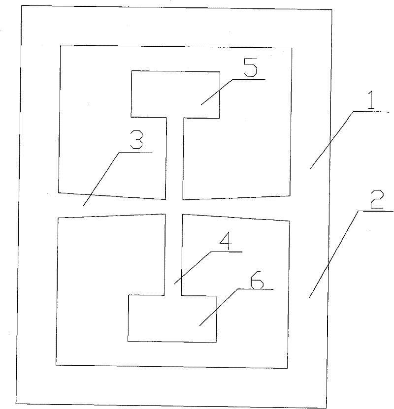
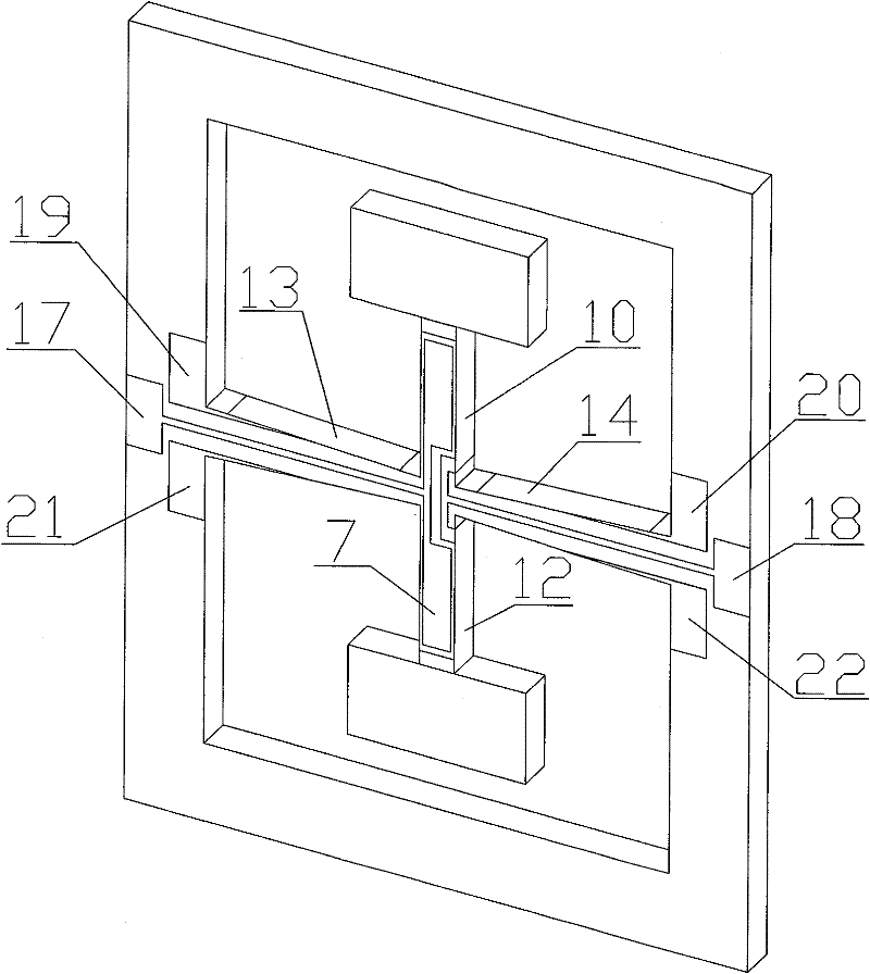
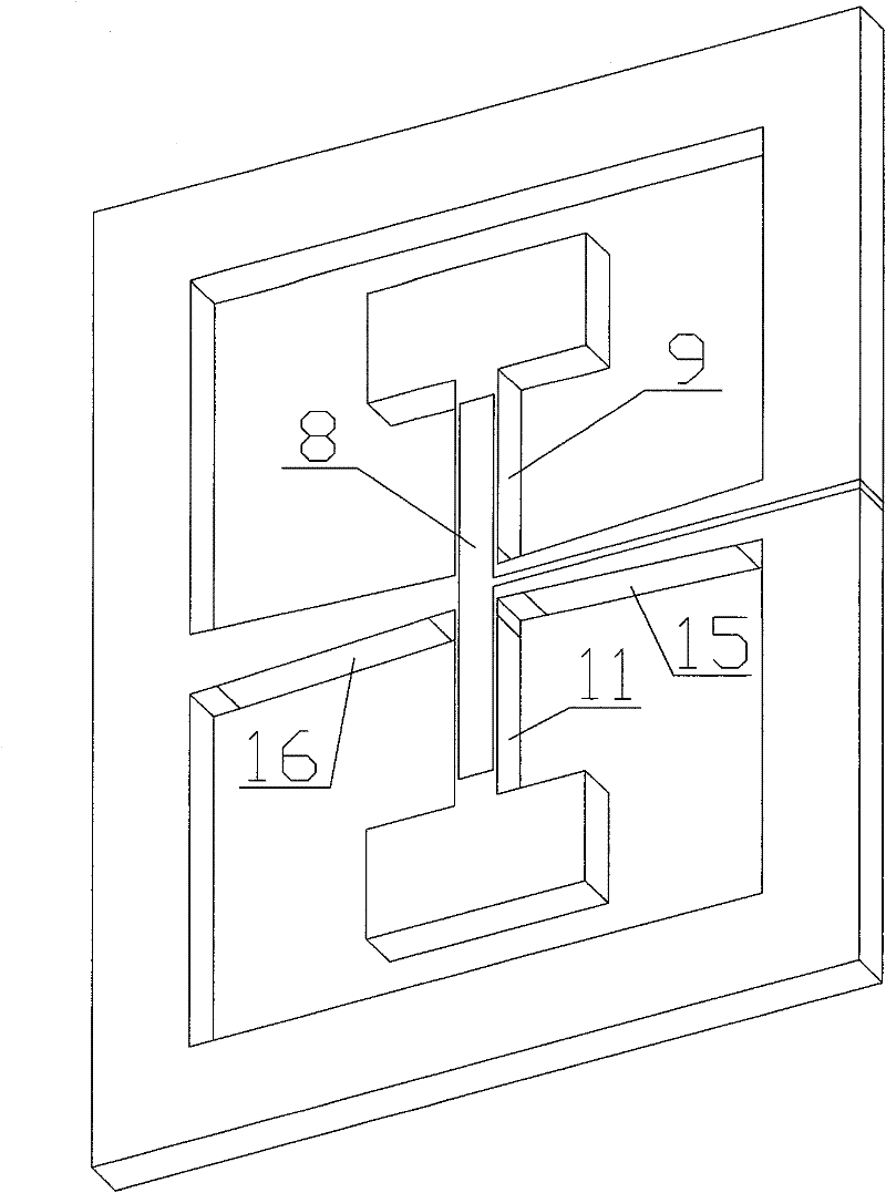
[0022] Embodiment 1: as figure 1 , figure 2 with image 3 As shown, the present invention is based on the cross-structure quartz micromechanical gyroscope for shear stress detection, including a substrate 1 and a gyroscope assembly connected together by bonding, and the gyroscope assembly includes a detection beam 3, more than one driving beam 4, The detection electrode and the driving electrode, the driving beam 4 and the detection beam 3 are arranged in a cross shape, the two ends of the driving beam 4 are provided with movable masses, the driving electrodes are installed on the outer surface of the driving beam 4, and the detection electrodes are installed on the outer surface of the driving beam 4. The outer surface of the beam 3 is detected. Both ends of the detection beam 3 are connected to a supporting frame 2 , and the driving beam 4 is located in the supporting frame 2 . The length direction of the driving beam 4 is along the Y crystal direction of the quartz, the...

Embodiment 2

[0029] Embodiment 2: as Figure 4As shown, the structure of this embodiment is basically the same as that of Embodiment 1, the difference being that: the two ends of the detection beam 3 are respectively connected with a supporting mass 23 to replace the supporting frame 2 . The working principle of this embodiment is the same as that of Embodiment 1, and will not be repeated here.

Embodiment 3

[0030] Embodiment 3: as Figure 5 As shown, the structure of this embodiment is basically the same as that of Embodiment 1, and the difference is that more than one opening 24 is opened on the detection beam 3 to reduce the internal stress of the detection beam 3 . The working principle of this embodiment is the same as that of Embodiment 1, and will not be repeated here.


PUM


Abstract

The invention discloses a shearing stress detection-based quartz micromechanical gyro with a criss-cross structure, which comprises a substrate and a gyro assembly connected together through bonding, wherein the gyro assembly comprises a detecting beam, more than one driving beam, a detecting electrode and a driving electrode; the driving beams and the detecting beam are arranged in a criss-crossmode; two ends of the driving beam are provided with movable mass blocks; the driving electrode is arranged on the outer surface of the driving beam; and the detecting electrode is arranged on the outer surface of the detecting beam. The shearing stress detection-based quartz micromechanical gyro with the criss-cross structure has the advantages of simple and compact structure, low cost, high sensitivity, simple manufacturing process and high rate of finished products.

Description

technical field [0001] The invention mainly relates to the design field of micro-mechanical gyroscopes, in particular to a cross-structure quartz micro-mechanical gyroscope. Background technique [0002] Compared with traditional gyroscopes, quartz micromechanical gyroscopes manufactured using micromechanical technology have the advantages of small size, light weight, low cost, high reliability, and mass production, and can be widely used in aviation, aerospace, weapons, automobiles, etc. , medical, consumer electronics and other fields have huge market potential and have become an important direction for the development of inertial gyroscopes. At present, micro-mechanical gyroscopes of various structures emerge in endlessly in the world, and their common feature is that they have two vibration directions perpendicular to each other, that is, the vibration excitation direction and the detection vibration direction caused by Coriolis force. [0003] At present, quartz gyrosc...

Claims


Application Information

Patent Timeline
Patent Type & Authority Patents(China)
IPC IPC(8): G01C19/56G01L1/16G01C19/5656
Inventor 吴学忠李圣怡谢立强肖定邦董培涛王浩旭满海鸥牛正一习翔
Owner NAT UNIV OF DEFENSE TECH
Why Eureka
Try Eureka