Spin Polarized Carrier Devices

A spin-polarized and carrier technology used in the field of polarimeters

Inactive Publication Date: 2012-02-08
HITACHI LTD
View PDF1 Cites 2 Cited by
  • Summary
  • Abstract
  • Description
  • Claims
  • Application Information

AI Technical Summary

Problems solved by technology

However, in the case of optically active samples, an additional rotation angle θ is required

Method used


Image

  • Spin Polarized Carrier Devices
  • Spin Polarized Carrier Devices
  • Spin Polarized Carrier Devices

Examples


Embodiment Construction

[0043] Device structure

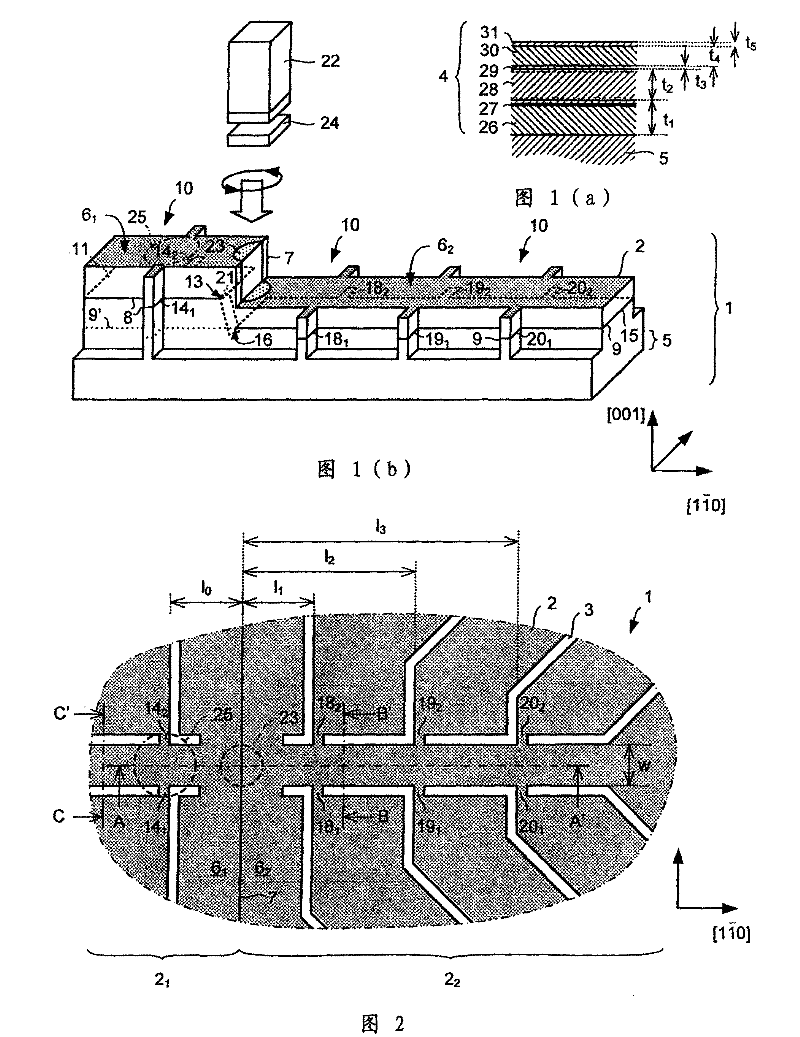
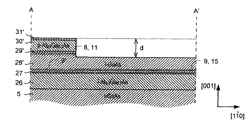
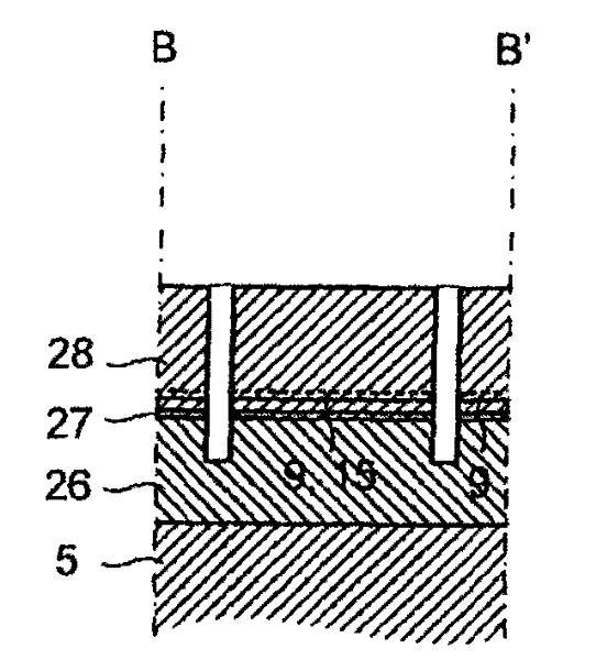
[0044] refer to Figure 1(b) , 1(a) and 2 to 5, show an electro-optic, spin-polarized carrier device. The device 1 comprises mesas 2 defined by trench isolation by using etched trenches 3 . The mesas 2 are used to pattern an aluminum gallium arsenide / gallium arsenide (AlGaAs / GaAs) heterostructure 4 on an undoped GaAs substrate 5 ( FIG. 1( a )). The mesa 2 is stepped with an upper unetched plane 6 1 and lower etch plane 6 2 . Thus, the mesa 2 is divided into a first and a second part 2 along the step edge 7 1 ,2 2 . Laddering the mesa 2 so that in the first part 2 of the mesa 2 1 Form two-dimensional hole gas (2DHG) 8 and the second part 2 of the mesa 2 2 A two-dimensional electron gas (2DEG) is formed9.

[0045] 2DEG 9 aggregates have sheet concentration n 2DEG =2.5×10 11 and mobility μ=3×10 3 cm 2 / Vs electrons. However, part 9' of 2DHG located below 2DHG 8 is depleted.

[0046] The mesa 2 comprises a hall bar structure 10 spanning th...


PUM

PropertyMeasurementUnit
thicknessaaaaaaaaaa
thicknessaaaaaaaaaa

Abstract

The present invention relates to a spin-polarized carrier device comprising: a carrier channel, including a non-ferromagnetic semiconductor, wherein the carriers exhibit spin-orbit coupling in the carrier channel; a semiconductor of the opposite conductivity type to the channel a region of material for forming a junction with the channel for injecting spin-polarized carriers into one end of the channel; and at least one wire connected to the channel for measuring a lateral voltage across the channel.

Description

technical field [0001] The present invention relates to a spin-polarized charge carrier device and more particularly, but not exclusively, to a polarimeter. Background technique [0002] Polarimeters can be used to measure changes in polarization induced by the optical rotation of materials such as anisotropic crystalline solids and liquids containing chiral molecules. [0003] A conventional polarimeter typically consists of a pair of linearly polarized mirrors and a photodetector, such as a photodiode. Light from a monochromatic source sequentially passes through a first polarizing mirror with a fixed orientation, a sample, and a second polarizing mirror (or "analyzer"). Photodetectors are used to detect the intensity of light reaching the photodetector from the analyzer. [0004] Rotating the analyzer relative to the first polarizing mirror changes the intensity of light reaching the photodetector. Therefore, in the absence of an optically active sample, the angle requ...

Claims


Application Information

Patent Timeline
Patent Type & Authority Patents(China)
IPC IPC(8): G01N21/21G01N21/17
CPCH01L29/66984G01J4/04G01J4/00
Inventor 耶尔格·冯德里西托马斯·琼沃思安德鲁·欧文杰洛·希诺娃
Owner HITACHI LTD
Why Eureka
Try Eureka