
Airplane complex construction member roughing unit automatic building method

An automatic construction and rough machining technology, applied in the direction of electrical program control, digital control, etc., can solve problems such as cumbersome operation, low processing efficiency, and affecting the aircraft manufacturing cycle

Inactive Publication Date: 2010-06-16
SHENYANG AIRCRAFT CORP +1
View PDF0 Cites 25 Cited by
  • Summary
  • Abstract
  • Description
  • Claims
  • Application Information

AI Technical Summary

Problems solved by technology

[0002] At present, the NC programming of complex components of aircraft generally uses the "NC machining" subsystem of the commercialized CAD / CAM software system. ), manually create processing operations, and set geometric parameter information, tool information, processing parameters, processing macros and other information, resulting in a very large amount of NC programming interaction, especially in order to reduce weight and ensure other performance requirements for current aircraft structural parts. It tends to be integrated and complicated, so that the structural parts have the characteristics of large number of features and many types of features. In this case, the use of manual interactive programming is cumbersome, heavy workload, and long programming cycle, resulting in low efficiency in programming parts
However, in the overall machining programming of aircraft structural parts, the workload of interactive programming is the largest, and the most cumbersome interactive operation belongs to the process of creating and editing machining operations of layered rough machining, and the number of layers of the NC machining program compiled is too many to be The processing capability of the tool is fully utilized, resulting in low processing efficiency, which in turn affects the entire aircraft manufacturing cycle

Method used


Image

  • Airplane complex construction member roughing unit automatic building method
  • Airplane complex construction member roughing unit automatic building method
  • Airplane complex construction member roughing unit automatic building method

Examples


Embodiment Construction

[0061] The embodiments of the present invention will be described in detail below in conjunction with the accompanying drawings. This embodiment is implemented on the premise of the technical solution of the invention, and detailed implementation methods and specific implementation processes are provided, but the protection scope of the present invention is not limited to The following implementation examples.

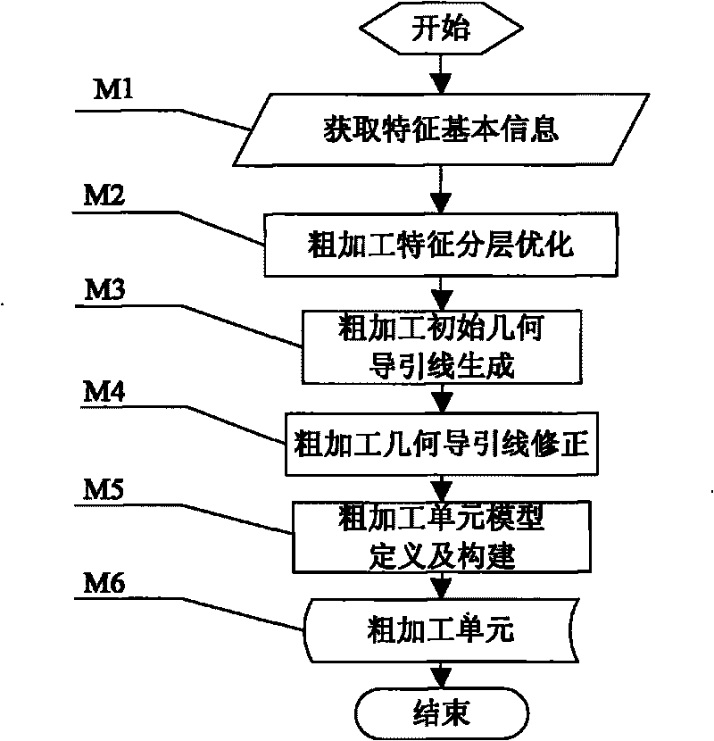
[0062] figure 1The general flow of the automatic construction method for the layered rough machining unit of the complex component of the aircraft, the method is mainly realized by the following steps, specifically: 1) Obtaining the basic information of the feature (M1); 2) The layered optimization of the rough machining feature (M2); 3 ) Generation of rough machining initial geometric guideline (M3); 4) Correction of rough machining geometric guideline (M4); 5) Definition and construction of rough machining unit model (M5). in:

[0063] The acquisition of feature ba...


PUM


Abstract

The invention relates to an airplane complex construction member roughing automatic building method. The method includes the main implementation process that: (1) characteristic basic information is acquired; (2) roughing characteristic is optimized by layering; (3) roughing initial geometric guide line is generated; (4) the roughing geometric guide line is corrected; (5) roughing unit model is defined and built, various parameter information is integrated, so as to be convenient for creating of processing operation and parameter setting. The invention is mainly used for automatically building roughing unit by layering after characteristic identification and cutter selection, so as to realize automatic generation of roughing processing operation and automatic acquiring and setting on the required geometric parameters, processing parameters, cutter parameters and transition macro parameters, further greatly reduce work load of man-machine interaction program, obviously shorten programming period and improve numerical control programming efficiency and processing efficiency.

Description

technical field [0001] The method for automatically constructing the rough machining unit of the aircraft complex component proposed by the present invention is used for the construction of the rough machining unit in the automatic programming module of the rapid numerical control programming system of the aircraft complex component, in order to realize the automatic generation of the rough machining tool path program, and then complete the aircraft structure The rough machining belongs to the field of aircraft digital intelligent machining technology. Background technique [0002] At present, the NC programming of complex components of aircraft generally uses the "NC machining" subsystem of the commercialized CAD / CAM software system. ), manually create processing operations, and set geometric parameter information, tool information, processing parameters, processing macros and other information, resulting in a very large amount of NC programming interaction, especially in o...

Claims


Application Information

Patent Timeline
IPC IPC(8): G05B19/19
Inventor 初宏震杜宝瑞郑国磊陈树林饶有福
Owner SHENYANG AIRCRAFT CORP
Learn More