
Plasma Display Panel

A display panel and plasma technology, applied in the direction of solid cathode components, cold cathode tubes, etc., can solve the problem that the discharge performance of the plasma display panel cannot be well exerted, and achieve the effect of overcoming bad factors and improving discharge performance

Inactive Publication Date: 2011-12-07
SICHUAN COC DISPLAY DEVICES
View PDF0 Cites 0 Cited by
  • Summary
  • Abstract
  • Description
  • Claims
  • Application Information

AI Technical Summary

Problems solved by technology

[0012] The purpose of the present invention is to provide a plasma display panel, which can solve the problem that the discharge performance of the plasma display panel using ITO less cannot be well exerted in the related art.

Method used


Image

  • Plasma Display Panel
  • Plasma Display Panel
  • Plasma Display Panel

Examples


Embodiment Construction

[0024] The present invention will be described in detail below with reference to the accompanying drawings and in combination with embodiments.

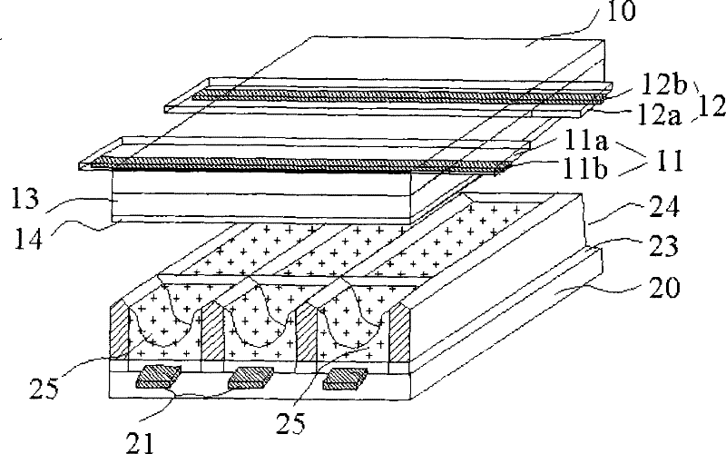
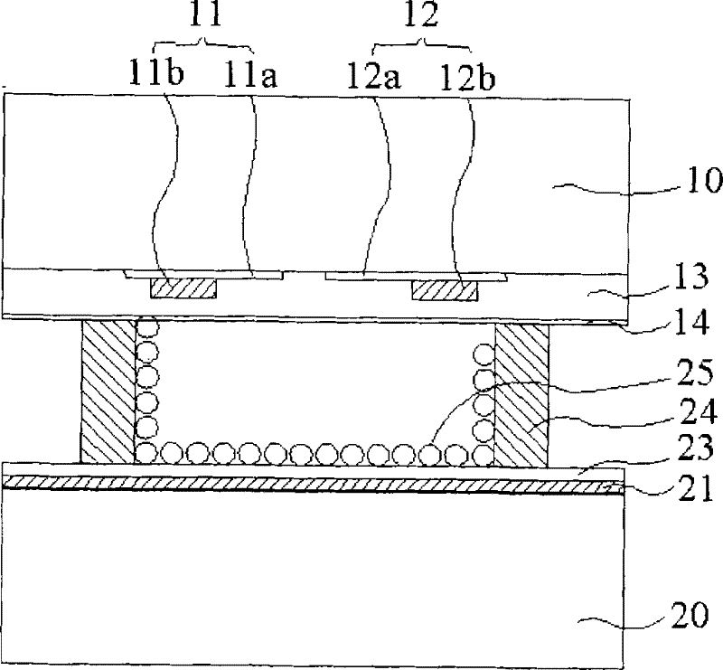
[0025] In the following embodiments, the plasma display panel may include such as figure 2 parts shown. For example, the plasma display panel in this embodiment includes: a front substrate 10 and a rear substrate 20 .

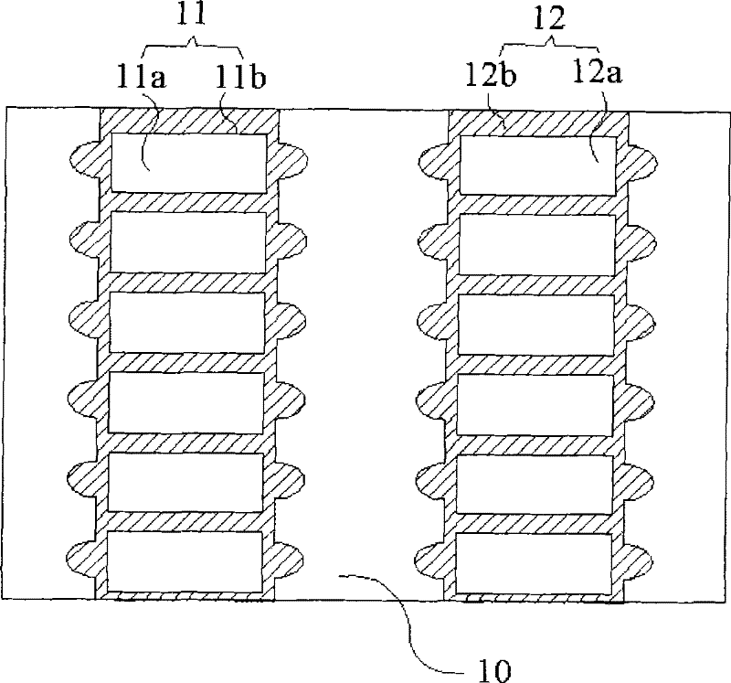
[0026] For the front substrate 10, the scan electrodes 11 and the sustain electrodes 12 are formed on the front substrate in parallel. In order to improve the contrast of the display screen, in the process of making the electrodes, black bars need to be added outside a group of scan electrodes and sustain electrodes. to increase the contrast of the display. Then, a layer of front dielectric layer 13 is covered on the top, and this dielectric layer can ensure the resistivity between the scan electrode 11 and the sustain electrode 12, and at the same time, a certain wall charge can be accumulated during plasma discha...


PUM


Abstract

The present invention provides a plasma display panel, which includes: a front substrate and a rear substrate, the front substrate has discharge electrodes, the rear substrate has barriers, and a display unit is formed between the barriers; Contacting the front substrate to form a sealed space with the barrier ribs and the front substrate, wherein the sealed space accommodates the discharge electrodes and the display unit. In the present invention, since the plasma display panel is divided into a plurality of sealed spaces for discharge by adopting a dividing part, many disadvantages of the existing ITO less type PDP in the production of a panel of more than 40 inches are overcome, The discharge performance of the plasma display panel of the present invention is improved.

Description

technical field [0001] The present invention relates to the field of flat display screens, and more particularly, to plasma display panels. Background technique [0002] The ion display panel (plasma display panel, PDP) is a 147nm vacuum ultraviolet ray generated when the inert mixed gas such as He+Xe, Ne+Xe, He+Ne+Xe or He+Ne+Kr+Xe is discharged in the vacuum cavity, so that the fluorescence The body emits light to achieve text and images that can be sensed visually. [0003] figure 1 is a schematic structural diagram of a plasma display panel according to the related art, and figure 2 is a sectional view of a plasma display panel according to the related art. refer to figure 1 with figure 2 A PDP (Plasma Display Panel, Plasma Display Panel) discharge unit with a three-electrode surface discharge structure mainly includes: scan electrodes 11 and sustain electrodes 12 formed on the front substrate 10, wherein the scan electrodes 11 and the sustain electrodes 12 are us...

Claims


Application Information

Patent Timeline
Patent Type & Authority Patents(China)
IPC IPC(8): H01J17/49H01J17/16H01J17/22H01J17/04
Inventor 陈立国
Owner SICHUAN COC DISPLAY DEVICES
Learn More