L1 multi-antenna relay station and power control method thereof

A power control, relay station technology, applied in radio relay systems, transmission control/equalization, communication between multiple stations, etc.

Inactive Publication Date: 2010-06-16
夏普高科技研发(上海)有限公司
View PDF3 Cites 14 Cited by
  • Summary
  • Abstract
  • Description
  • Claims
  • Application Information

AI Technical Summary

Problems solved by technology

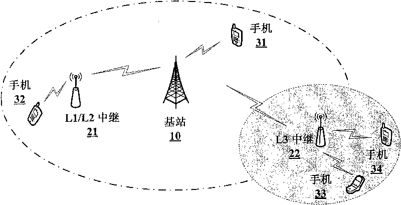
Therefore, the signal-to-noise ratio at the location of the L1 relay station 21 will be the upper limit of the receiving signal-to-noise ratio that the terminal (mobile phone 32) in its coverage area can achieve

Method used


Image

  • L1 multi-antenna relay station and power control method thereof
  • L1 multi-antenna relay station and power control method thereof
  • L1 multi-antenna relay station and power control method thereof

Examples


Embodiment Construction

[0105] The preferred embodiments of the present invention will be described in detail below with reference to the accompanying drawings, and unnecessary details and functions for the present invention will be omitted during the description to avoid confusing the understanding of the present invention.

[0106] In order to clarify and describe the implementation steps of the present invention in detail, some specific embodiments of the present invention are given below, which are applicable to the LTE-A cellular communication system. It should be noted that the present invention is not limited to the applications described in the embodiments, but is applicable to other communication systems.

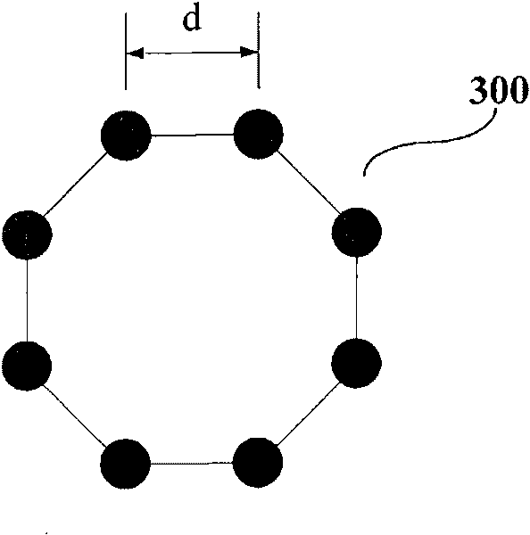
[0107] In the future IMT-Advanced system, both the base station and the terminal will use more antennas for receiving and transmitting. In this specification, it is assumed that the base station uses M=8 antennas for transmission and reception, and the mobile terminal uses N=8 antennas fo...


PUM


Abstract

The invention provides an L multi-antenna relay station and a power control method thereof. Particularly, the relay station comprise a receiving device, a transmitting device, an information acquisition device, a route user equipment selecting device and a power control device. The receiving device is used for receiving down receiving signals from a base station and up receiving signals from user equipment; the transmitting device is used for transmitting up transmitting signals to the base station and down transmitting signals to the user equipment; the information acquisition device is used for conducting down link synchronization with the base station to acquire relevant information of the base station and control information of all user equipment in a servo small area of the base station; the route user equipment selecting device is used for determining a set of user equipment which decides to use the relay station for transitroute on the basis of a large scale fading rule or a signal to noise ratio rule; and the power control device is used for conducting power control on the user equipment in the set of the decided user equipment and partially or completely compensating the large scale fading between the relay station and the base station.

Description

technical field [0001] The present invention relates to a cellular mobile communication system, and more particularly relates to a multi-antenna configuration and power control scheme of an L1 relay station, which is suitable for a mobile communication system using relay technology. Background technique [0002] With the development of information technology, mobile terminals have higher and higher requirements for access rate, which makes the future mobile communication system have higher transmission rate, which leads to the reduction of the coverage area of ​​traditional cells. The basic function of the wireless relay is to use the relay node to reprocess the signal of the base station before sending it out, expand the coverage of the cell, reduce the dead zone areas in communication, and at the same time balance the load and transfer the business in the hotspot area. Introducing a relay can also save the transmit power of the terminal, thereby extending battery life. In...

Claims


Application Information

Patent Timeline
Patent Type & Authority Applications(China)
IPC IPC(8): H04B7/005H04B7/14H04B7/26
Inventor 张应余刘仁茂丁铭黄磊孙国林陈晨
Owner 夏普高科技研发(上海)有限公司
Why Eureka
Try Eureka