Light projector for scanning module

A technology of light source projection and scanning module, applied in the direction of light source, electric light source, point light source, etc., can solve the problems of image distortion, reduced intensity, poor image brightness quality, etc., to solve the problem of reduced light intensity, improved quality, and increased light effect of brightness

Inactive Publication Date: 2010-06-16
TECO IMAGE SYST
View PDF0 Cites 4 Cited by
  • Summary
  • Abstract
  • Description
  • Claims
  • Application Information

AI Technical Summary

Problems solved by technology

However, this method cannot improve the signal/noise ratio. After the brightness at both ends is compensated and amplified by the firmware (F/W), the noise will also be amplified, which will still cause image distortion.
[0005] In addition to the above-mentioned way of firmware (F/W) compensati...

Method used


Image

  • Light projector for scanning module
  • Light projector for scanning module
  • Light projector for scanning module

Examples


Embodiment Construction

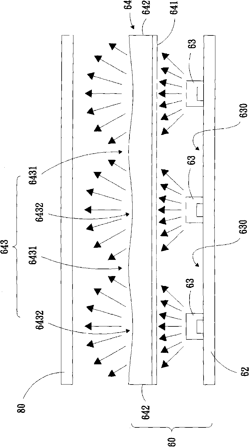
[0045] Please refer to image 3 , Figure 4 , Figure 5A and Figure 5B , is the first embodiment of the present invention, image 3 is a front view diagram, Figure 4 is a schematic side view, Figure 5A is a schematic diagram of the substrate and light-emitting diodes, Figure 5B A schematic diagram of a diffuser plate.

[0046] The light source projection device 60 of the scanning module includes: a substrate 62 , a plurality of LEDs 63 , and a diffusion plate 64 .

[0047] The substrate 62 is generally in the shape of a strip, wherein the two ends and the middle section of the substrate 62 can preferably be located on the same horizontal plane, but the present invention is not limited thereto, and the two ends and the middle section of the substrate 62 can also be located on different horizontal planes And for the curved plate body.

[0048] A plurality of light-emitting diodes 63 are arranged on the substrate 62 along the horizontal direction (X-axis) (such as F...


PUM


Abstract

The invention relates to a light projector for a scanning module, which comprises a substrate, a plurality of light-emitting diodes and a diffuser plate, wherein the light-emitting diodes are positioned on the substrate and are used for generating a plurality of incident rays; the diffuser plate is positioned on the side edge of the substrate and comprises a first plane, two end faces and a second plane; the first plane is used for receiving the plurality of incident rays; the two end faces are connected to both ends of the first plane in a direction of a horizontal axis; both ends of the second plane are connected to the two end faces respectively to diffuse the plurality of incident rays to scanning files; the second plane comprises a plurality of second horizontal concave parts for diffusing the plurality of incident rays and a plurality of second horizontal convex parts for aggregating the plurality of incident rays; and the plurality of second horizontal convex parts and the plurality of second horizontal concave parts are arranged in a staggered mode in the direction of the horizontal axis, so that the plurality of incident rays are diffused to the scanning files uniformly.

Description

technical field [0001] The invention relates to a light source projection device, in particular to a light source projection device for a scanning module. Background technique [0002] With the advancement of technology, optical scanners have become increasingly popular computer peripheral devices. Optical scanners capture images mainly by using a light-emitting device to irradiate light onto the document to be scanned. After the light is reflected by the document to be scanned, the light is guided to the photosensitive component by the lens group, and the photosensitive component can detect different areas on the document. Reflect light of different intensities, and convert the reflected light waves into digital data, and then use scanning software to read in the data and reassemble it into computer image files. [0003] see figure 1 and figure 2 As shown, the ideal light-emitting device should have a uniform brightness distribution, but because most of the current scan...

Claims


Application Information

Patent Timeline
IPC IPC(8): H04N1/00F21S2/00F21V5/08F21Y101/02F21W131/403
Inventor 罗新保陈三塘
Owner TECO IMAGE SYST
Why Eureka
Try Eureka