Supercharge Your Innovation With Domain-Expert AI Agents!

Modular Tooling System

A tool system, modular technology, applied in the direction of tools, tool holders, manufacturing tools for lathes, etc., can solve the problems of only mentioning the coolant, changing the adjustment of selection, etc., and achieve the effect of eliminating leakage

Inactive Publication Date: 2011-12-21
KENNAMETAL INC
View PDF5 Cites 0 Cited by
  • Summary
  • Abstract
  • Description
  • Claims
  • Application Information

AI Technical Summary

Problems solved by technology

Here too there is the danger that the selected regulation will be changed so that the coolant is clearly only raised up to a maximum pressure of 10 bar

Method used


Image

  • Modular Tooling System
  • Modular Tooling System
  • Modular Tooling System

Examples


Embodiment Construction

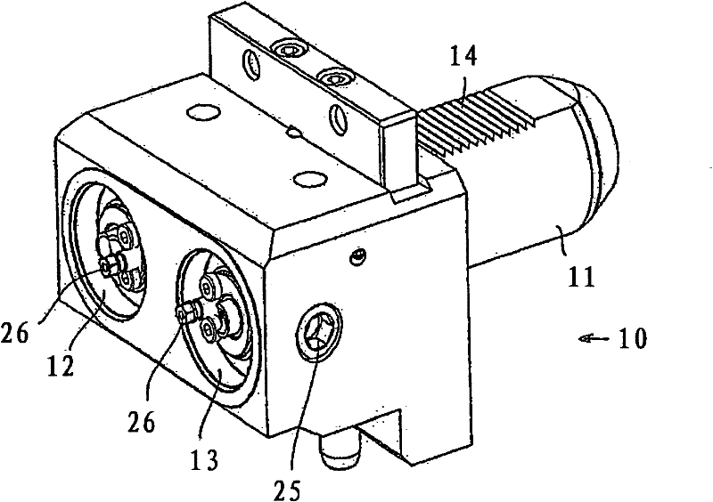
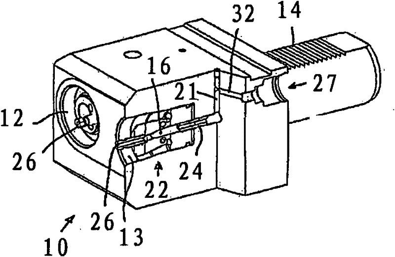
[0024] exist figure 1 The basic tool holder 10 shown in has a clamping rod 11 and two receiving openings 12, 13, which are formed for the insertion of the tool holder rod. Here special consideration is given to hollow rod cones, as shown by Figure 3 to Figure 5 As can be seen. The rod 11 has a grid profile 14 on the upper side.

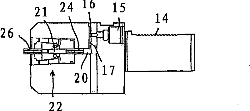
[0025] as by Figure 2bAs can be partially seen, two side-by-side openings 15 are provided on the rear side of the basic tool holder 10 , to which openings a high-pressure line for the coolant supply can be connected starting from the machine side. Port 15 and the coolant input described below are for pressures > 100 bar (10 7 Pa) for design. The diameter is continuously reduced to a smaller size relative to the inlet 15 , after which the hole ultimately leads into a transverse hole 16 or 17 which is closed at the end with a plug 18 . The transverse bore is necessary in order to lead off the coolant flow from the area of ​​the clamping device o...


PUM


Abstract

The invention relates to a modular tool system, made up of a base tool holder with at least one housing drilling for the shaft of a tool support which may be fixed by a clamping device and comprises a cutting insert for machine cutting, in particular, turning of workpieces, wherein coolant lines run through the base tool holder and the tool support through a supply line by means of which a pressurised, in particular, highly pressurised coolant may be supplied to the region of the relevant active cutting edge. According to the invention, each connector point between two adjacent components of the tool system with the faces thereof in contact is bridged by a tube body, preferably with a threaded connection, wherein the tube body opens out in provided drillings in the components which are sealed to the outside.

Description

technical field [0001] The invention relates to a modular tool system comprising a basic tool holder with at least one receiving hole for a rod of a tool holder which can be fixed via a clamping device and has a tool holder for cutting In particular for tool heads for turning workpieces, in which a plurality of coolant lines are guided through the basic tool holder and the tool holder via a supply line, through which coolant lines are supplied under pressure, especially under high pressure The coolant can be directed to each effective cutting edge. Background technique [0002] Coolants or cooling lubricants play an important role in the cutting process. In cutting operations such as turning, milling and drilling, high temperatures occur at the active cutting edge which removes chips from the workpiece, which accelerates the wear of the tool (tip). The reason for the temperature rise at the cutting edge of the tool is that the specific heat and the thermal conductivity of ...

Claims


Application Information

Patent Timeline
Patent Type & Authority Patents(China)
IPC IPC(8): B23B27/10B23B29/04B23B31/02
CPCB23B31/006B23B27/10B23B29/046B23B31/02B23B2250/12
Inventor H·施托希G·林德纳
Owner KENNAMETAL INC
Features
  • R&D
  • Intellectual Property
  • Life Sciences
  • Materials
  • Tech Scout
  • Unparalleled Data Quality
  • Higher Quality Content
  • 60% Fewer Hallucinations
Learn More