Frictional part with a zig-zag or undulating circumferential groove in the frictional surface

A technology of friction parts and friction surfaces, applied in the direction of friction linings, friction clutches, clutches, etc., which can solve the problems of limited controllability of friction devices and undesired torque transmission, etc., and achieve the effect of improving wear characteristics

Active Publication Date: 2010-06-16
BORGWARNER INC
View PDF0 Cites 12 Cited by
  • Summary
  • Abstract
  • Description
  • Claims
  • Application Information

AI Technical Summary

Problems solved by technology

Moreover, it has been found that the controllability of the friction action device is limited when using known friction components
Furthermore, the known groove patter...

Method used


Image

  • Frictional part with a zig-zag or undulating circumferential groove in the frictional surface
  • Frictional part with a zig-zag or undulating circumferential groove in the frictional surface
  • Frictional part with a zig-zag or undulating circumferential groove in the frictional surface

Examples


Embodiment Construction

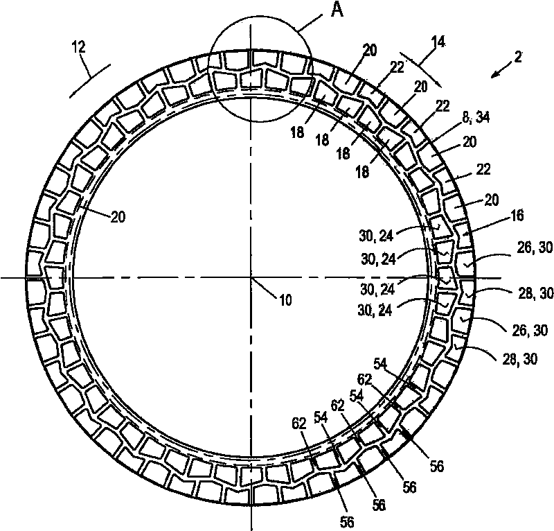
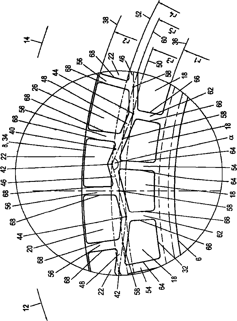
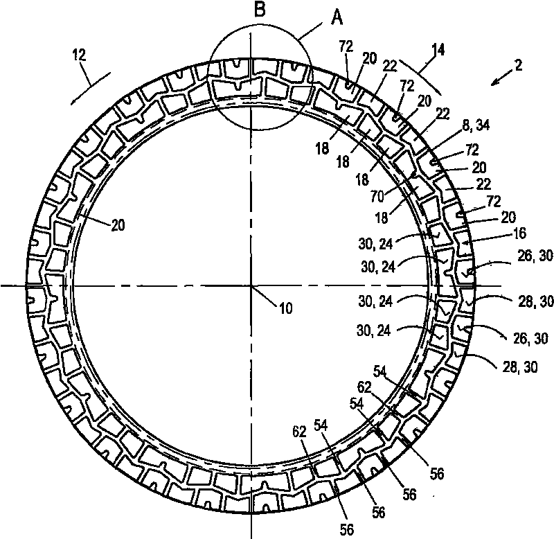
[0049] figure 1 with figure 2 A first embodiment of the friction member 2 for the friction acting device according to the present invention is shown. The friction component 2 shown in this solution is implemented as a plate for a multi-plate clutch or a multi-plate brake and has a friction lining carrier 4. The friction lining carrier 4 is embodied as an annular steel disk, which extends in the plane of the drawing and includes an inner edge 6 and an outer edge 8. Provided on the inner rim 6 is a drive profile, preferably an internal toothing, which is only schematically represented in the figures and is integral with the annular disc. The internal tooth shape is used to fixedly connect the friction member 2 to a sheet carrier in the sense of rotation, but enables the friction member 2 to move in an axial direction of the sheet carrier. The present friction member 2 is therefore a so-called inner sheet. It should be noted, however, that the friction member 2 according to the...


PUM


Abstract

The present invention relates to a frictional part (2) for a device operating in a frictionally engaged fashion, said part having an annular frictional surface (30) comprising an inner edge (32) and an outer edge (34), wherein a circumferential first groove (40) is provided extending in the frictional surface (30) between radially interior and radially exterior deflection points (44, 42) in a zig-zag or undulating fashion, a plurality of second grooves (54) is provided that originate from the inner edge (32) and extend to the exterior deflection points (42), and a plurality of third grooves (56) is provided that extend from the outer edge (34) into the circumferential first groove (40). According to the invention, the third grooves (56) open at opening points (58) disposed between the deflection points (42, 44) in the circumferential first groove (40).

Description

Technical field [0001] The present invention relates to a friction component, such as a friction plate used in a friction action device (such as a multi-plate clutch). The friction component has an annular friction surface having an inner edge and an outer edge. A peripheral first groove is provided in the friction surface, and the peripheral first groove extends in a zigzag or wave form between the radially inner and radially outer deflection points. Background technique [0002] The prior art discloses a variety of friction components for friction action devices, especially plates for multi-plate clutches. These plates basically include an annular friction lining carrier and a friction lining, the friction lining is attached It is connected to at least one side of the friction lining carrier to form an annular friction surface. The friction lining generally includes a fibrous material produced from a paper-containing material, or otherwise produced from carbon. In contrast, t...

Claims


Application Information

Patent Timeline
IPC IPC(8): F16D13/64F16D13/72
CPCF16D2069/004F16D13/72F16D13/648
Inventor E·法布里修斯V·雷涅
Owner BORGWARNER INC
Why Eureka
Try Eureka