

High speed pressing and forming method of warm powder and device thereof
A high-speed pressing and powder technology, applied in the field of powder metallurgy, can solve the problems of restricting research and development, unable to achieve high-speed pressing and forming of warm powder, and achieve the effects of avoiding uneven density distribution, simple structure and low cost.
- Summary
- Abstract
- Description
- Claims
- Application Information
AI Technical Summary
Problems solved by technology
Method used
Image


Examples
Embodiment 1
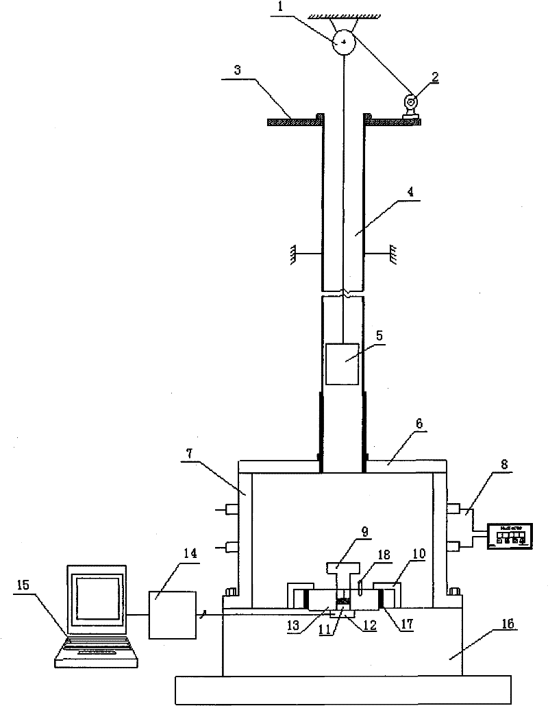
[0028] A warm powder high-speed pressing forming method is an integrated technology of warm pressing and high-speed pressing forming. This technology uses a motor to adjust the falling height of the hammer to obtain different impact velocities under different falling heights of the hammer. The impact stress wave transmits energy to the warm powder through the upper die punch, so that the warm powder can be formed rapidly and densely. The warm powder high-speed compression molding device that realizes the above method is as figure 1 As shown, it includes a fixed pulley 1, a motor 2 with a model of MR5130 and a power of 40W, a frame 3, a guide cylinder 4, a hammer with a mass of 10kg 5, an upper template 6, a side template 7, and a photoelectric sensor and a pulse meter. Partially composed speedometer 8, in which the photoelectric sensor is BR20M-TDTL through-beam photoelectric sensor, upper and lower die punches 9, 11, pressure plate 10, model CYL203, pressure sensor 12 with a ...
Embodiment 2
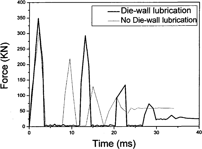
[0034] This embodiment adopts the mold wall lubrication technology on the basis of Example 1, that is, evenly coats 1 μm thick HW absolute ethanol suspension in the cavity of the mold 13. Example 1 is the same. figure 2 It is the shock wave suppression curve under the condition of using or not adopting the mold wall lubrication technology in the method of the present invention. from figure 2 The maximum impact force is 349.1KN, the action time is about 34ms, and the green density of the sample is 7.61g / cm 3 , The green stripping force is 45.3KN. It can be seen that the combination of warm powder high-speed pressing and mold wall lubrication technology increases the maximum impact force by about 42.8KN, and prolongs the action time of powder by about 12ms, thus further increasing the density of the green body and reducing the demoulding force, so that the powder metallurgy products can reach a high level. The level is nearly finalized.
PUM
| Property | Measurement | Unit |
|---|---|---|
| Density | aaaaa | aaaaa |
Abstract
Description
Claims
Application Information