Highly-efficient flow control sieve tube

A flow screening, high-efficiency technology, applied in the direction of production fluid, wellbore/well components, earthwork drilling and production, etc.

Active Publication Date: 2010-06-23
ANTON OILFIELD SERVICES (GRP) LTD
View PDF0 Cites 7 Cited by
  • Summary
  • Abstract
  • Description
  • Claims
  • Application Information

AI Technical Summary

Problems solved by technology

[0010] The technical problem to be solved by the present invention is to overcome the defects of the prior art and provide a high-efficiency flow control screen, which can well solv

Method used


Image

  • Highly-efficient flow control sieve tube
  • Highly-efficient flow control sieve tube
  • Highly-efficient flow control sieve tube

Examples


Embodiment Construction

[0033] In order to make the object, technical solution and advantages of the present invention clearer, the implementation manner of the present invention will be further described in detail below in conjunction with the accompanying drawings.

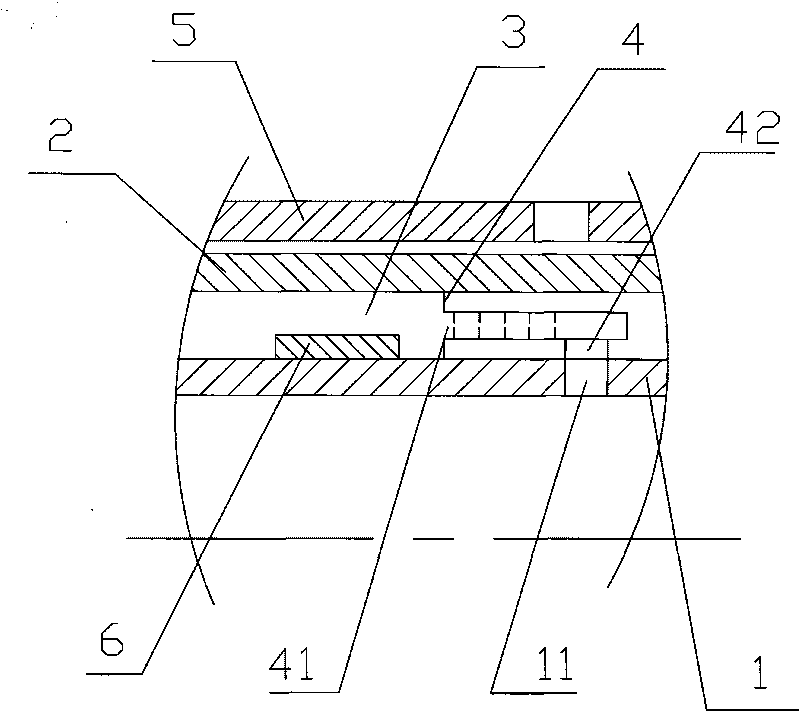
[0034] Such as figure 1 As shown, the present invention is a high-efficiency flow control screen, the screen includes a base pipe 1, the base pipe is provided with a base pipe inlet 11, the base pipe is covered with a filter sleeve 2, between the base pipe and the filter sleeve The annular seam between them is the diversion layer 3; the screen is provided with a flow control device 4, the inlet 41 of the flow control device communicates with the diversion layer, and the outlet 42 of the flow control device communicates with the inlet of the base pipe.

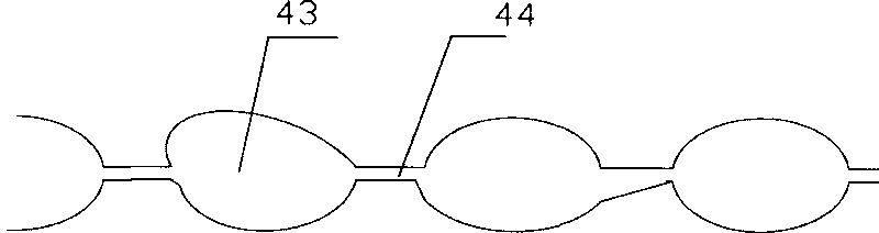
[0035] Such as figure 2 , image 3 , Figure 4 with Figure 5 As shown, the flow control device includes a flow control flow channel, the flow control flow channel is formed by a p...


PUM


Abstract

The invention discloses a highly-efficient flow control sieve tube. The sieve tube comprises a parent tube, wherein the parent tube is provided with a parent tube inlet; a filtering sleeve is sleeved outside the parent tube; a circumferential seam between the parent tube and the filtering sleeve is a flow deflecting layer; and the sieve tube is provided with a flow control device of which an inlet is communicated with the flow deflecting layer, while an outlet is communicated with the parent tube inlet. Under the condition of the relatively greater viscosity ratio of oil water, the sieve tube of the invention is cased off so that water yield is greatly reduced and oil production is slightly reduced. Before the surface of the oil water reaches the sieve tube, the flow velocities of a fluid at each position along a production section are substantially the same, which plays a role in controlling the uniform advancing of the oil water and delaying water breakthrough time.

Description

technical field [0001] The invention relates to a screen pipe used in the field of oilfield exploitation, in particular to a high-efficiency flow control screen pipe. Background technique [0002] In oil extraction operations, screen pipes (also known as sand control pipes) are used for sand control and filtration of oil wells, gas wells, horizontal wells, vertical wells and directional wells. During the production operation, the screen pipe is lowered into the oil well, and there is an annulus between the screen pipe and the well wall. The screen tube includes a base pipe, on which through holes are uniformly distributed as the inlet of the base pipe, and a filter sleeve is placed outside the base pipe, and the annular seam between the base pipe and the filter sleeve is a flow-guiding layer. [0003] The development of most oil reservoirs is to drive the oil to the oil well through water, so that the crude oil flows from the deep part of the oil reservoir to the well, so a...

Claims


Application Information

Patent Timeline
IPC IPC(8): E21B43/08
Inventor 裴柏林房娜
Owner ANTON OILFIELD SERVICES (GRP) LTD
Why Eureka
Try Eureka