Ventilating passage for crankcase ventilating system

A crankcase ventilation and ventilation channel technology, which is applied to crankcase ventilation, engine components, machines/engines, etc., can solve the problems of poor separation effect and large separation pressure, so as to improve intake air quality, improve combustion and emissions, The effect of reducing the content of lubricating oil

Active Publication Date: 2012-06-27
CHERY AUTOMOBILE CO LTD
View PDF0 Cites 0 Cited by
  • Summary
  • Abstract
  • Description
  • Claims
  • Application Information

AI Technical Summary

Problems solved by technology

At present, most of the oil-gas separation devices are installed on the valve chamber cover (also known as the cylinder head cover). At the inlet of the oil-air separator, between the cylinder head ventilation channel and the inlet of the oil-air separator, the oil-air mixture is in contact with the lubricating oil on the upper part of the cylinder head, so the oil-air mixture entering the oil-air separator carries more oil, which brings a large separation pressure to the oil-gas separation device, and the separation effect is not good
[0004] That is, there are the following technical problems in the prior art: between the cylinder head ventilation channel and the inlet of the oil-air separation device, the oil-air mixture is in contact with the lubricating oil on the upper part of the cylinder head, and it is impossible to avoid the oil-air mixture and the lubricating oil before the inlet of the oil-air separation device. direct contact

Method used


Image

  • Ventilating passage for crankcase ventilating system
  • Ventilating passage for crankcase ventilating system

Examples


Embodiment Construction

[0020] The present invention will be described in detail below according to the accompanying drawings, which is a preferred embodiment among various implementations of the present invention.

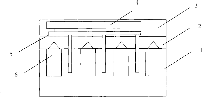
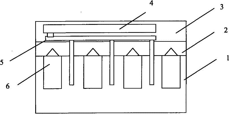
[0021] Refer to attached figure 1 : in the figure

[0022] 1---Cylinder block 2---Cylinder head 3---Cylinder cover 4---Oil-air separator 5---Ventilation channel 6---Cylinder. Ventilation passages are distributed on the cylinder block, cylinder head and cylinder head cover. Inside the cylinder head, a separate ventilation passage is produced through processing to completely avoid direct contact with lubricating oil; inside the cylinder head cover, the passage formed by processing will The oil-air mixture from the cylinder head channel is directly introduced into the inlet of the oil-air separator to avoid direct contact with the lubricating oil; in addition, at the junction of the three parts of the cylinder block, cylinder head and cylinder head cover, the design of the O-ring seal met...


PUM


Abstract

The invention relates to a ventilating passage for a crankcase ventilating system. The passage comprises a cylinder cover ventilating passage and an oil-gas separation device, wherein a sealing pipeline is adopted between the cylinder cover ventilating passage and the inlet of the oil-gas separation device for gas conveying to prevent fuel air mixture and lubricant oil from directly contacting before the inlet of the oil-gas separation device so as to effectively reduce the content of the lubricant oil in the fuel air mixture and directly improve the effect of oil-gas separation. The ventilating passage is advantageous to improve the air intake quality in an induction manifold, and improve combustion and exhaust.

Description

technical field [0001] The invention relates to a crankcase ventilation system of an engine, in particular to a ventilation channel of the crankcase ventilation system. Background technique [0002] The engine crankcase ventilation system is a device that separates the exhaust gas (caused by the leakage of the piston ring and the valve guide) that remains inside the engine during the combustion process and introduces it into the intake system for combustion in the cylinder again. It is a device to improve combustion and emissions. The crankcase ventilation system consists of an in-cylinder ventilation passage, an oil-air separation device, a PCV valve, an external ventilation passage, an intake manifold and an intake hose. After the oil-gas mixture in the cylinder is exported through the internal channel, the oil-gas separation is carried out in the oil-gas separation device, and the separated gas enters the intake manifold and intake hose (selected by the PCV valve) throug...

Claims


Application Information

Patent Timeline
Patent Type & Authority Patents(China)
IPC IPC(8): F01M13/04
Inventor 李志勇
Owner CHERY AUTOMOBILE CO LTD
Why Eureka
Try Eureka