Device and method for controlling water vapor in application of testing solid oxide fuel cell

A technology of solid oxide and fuel cells, which is applied in the direction of measuring devices, measuring electricity, and measuring electrical variables, etc., which can solve the problems of device structure redundancy, large calculation process errors, and low accuracy

Active Publication Date: 2010-06-23
NINGBO INST OF MATERIALS TECH & ENG CHINESE ACADEMY OF SCI
1 Cites 8 Cited by

AI-Extracted Technical Summary

Problems solved by technology

The water vapor method in the above-mentioned patent is calculated by the ideal gas state equation. The calculation process has large errors and low accuracy. This calculat...

Abstract

The invention relates to a device and a method for controlling water vapor in an application of testing a solid oxide fuel cell. The device comprises a water tank, a metering pump, a first one-way valve, an evaporator, a gas flow controller, a second one-way valve, a mixer, a heater and a heating tape, wherein the water tank, the metering pump, the first one-way valve, the evaporator and the mixer are connected in sequence; the gas flow controller, the second one-way valve and the mixer are connected in sequence; the mixer and the evaporator are placed in a heating cavity of the heater; a pipeline between the outlet of the water tank and the inlet of the metering pump is provided with a first temperature sensor and a first pressure sensor; the mixer is provided with a second temperature sensor and a second pressure sensor; and a fuel gas inlet pipe is provided with a third temperature sensor. Compared with the prior art, the method and the device have the advantages of leading the control and measurement for the water vapor to be more convenient and more accurate without a humidity measurement device and considering the influence of temperature and pressure to the volume of the water vapor, and are suitable for high pressure environment.

Application Domain

Electrical testing

Technology Topic

Measurement deviceEvaporator +12

Image

  • Device and method for controlling water vapor in application of testing solid oxide fuel cell
  • Device and method for controlling water vapor in application of testing solid oxide fuel cell
  • Device and method for controlling water vapor in application of testing solid oxide fuel cell

Examples

  • Experimental program(1)

Example Embodiment

[0033] The present invention will be further described in detail below with reference to the embodiments of the accompanying drawings.
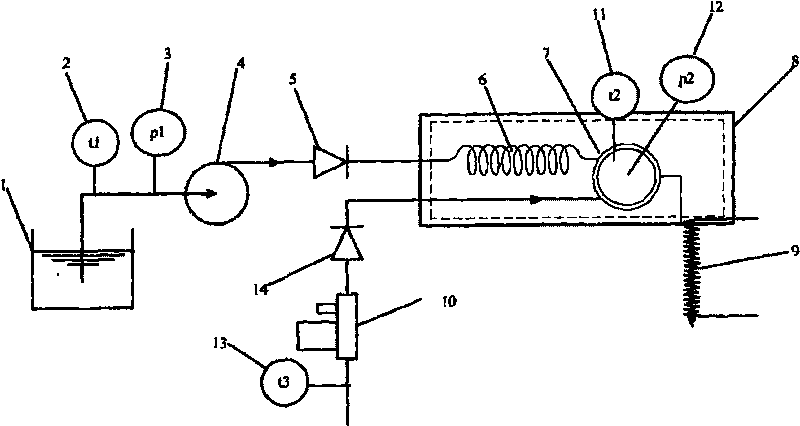
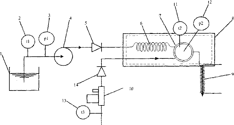
[0034] figure 1 The shown control device for water vapor in a solid oxide fuel cell test application includes a water tank 1, a first temperature sensor 2, a second pressure sensor 3, a metering pump 4, a first one-way valve 5 connected by pipes , evaporator 6 , mixer 7 , heater 8 , heating belt 9 and gas flow controller 10 , second temperature sensor 11 , second pressure sensor 12 , third temperature sensor 13 , second one-way valve 14 .
[0035] The water tank 1 is filled with liquid distilled water, the metering pump 4 is used to adjust the flow of liquid water, the outlet of the water tank 1 is connected with the inlet of the metering pump through a pipeline, and the first temperature sensor 2 and the first pressure sensor 3 are arranged at the outlet of the water tank and the metering pump. On the pipeline between the inlets, it is used to measure the temperature and pressure of the liquid water entering the metering pump 4; the outlet of the metering pump is connected to the inlet of the first one-way valve 5, and the first one-way valve 5 is used to prevent the backflow of liquid water, The outlet of the first one-way valve 5 and the inlet of the evaporator 6, the evaporator 6 is used to turn liquid water into water vapor, the outlet of the evaporator 6 and the first inlet of the mixer 7, and the inlet of the gas flow controller 10 and The fuel gas inlet pipe is connected, the gas flow controller 10 is used to control the gas flow of the fuel gas flow, the outlet of the gas flow controller 10 is connected with the inlet of the second one-way valve 14, and the second one-way valve 14 can prevent the backflow of the fuel gas, The outlet of the second one-way valve 14 is connected to the second inlet of the mixer 7. The mixer 7 is used to fully mix the water vapor and the fuel gas. The outlet of the mixer 7 is connected to the cell stack or the anode inlet of the single cell through a pipeline. Connected, or connected with the inlet of the pre-reformer, the outlet pipe of the mixer 7 is wrapped with a heating belt 9, and the heating belt 9 can prevent the water vapor in the mixed gas from condensing and separating out. The heating belt 9; the mixer 7 and the evaporator 6 It is placed in the heating cavity of the heater 8; the second temperature sensor 11 and the second pressure sensor 12 are installed in the mixer 7, and the third temperature sensor 13 is installed in the fuel gas intake pipe.
[0036] The control process of the device is as follows: First, determine the flow rate of fuel gas according to the specific operating conditions in the system, and adjust the flow rate Q of fuel gas through the gas flow controller 10 f , through the first temperature sensor 2, the second pressure sensor 3, the second temperature sensor 11, the second pressure sensor 12, and the third temperature sensor 13 to measure the temperature and pressure parameters t1, t2, t3, p1, p2 at each position , through the temperature sensor and pressure sensor, according to the latest standard calculation model of water and water vapor published by the International Federation of Water and Water Vapor Properties (IAPWS), that is, the IAPWS-IF97 formula, the density of water at temperature t1 and pressure p1 is calculated to be ρ1, The density of water at temperature t2 and pressure p2 is ρ2, and the volume flow of fuel gas is Q f The required water vapour content is Y w , so the volume flow Q of liquid water is calculated w Adjust the flow rate of the metering pump to Q 1,w That's it.
[0037] To give an example to help understand the control process of the whole method, set the inlet temperature of the gas flow controller 10 t3=25°C, and the passing flow rate of the fuel gas hydrogen is Q f =100ml/min, the inlet pressure of the metering pump 4 is p1=101.325KPa, the temperature is t1=25℃, the temperature in the mixer 7 is t2=150℃, the pressure is P2=101.325KPa, the water vapor content of the system to be controlled is Y w =90%, according to the IAPWS-IF97 formula of water and water vapor properties, the density of water at temperature t1 (°C) and pressure P1 (KPa) is calculated as ρ1=997.05 (kg/cm 3 ), the density of water at temperature t2 (°C) and pressure p2 (KPa) is ρ2 = 0.52 (kg/cm 3 ), so the liquid water flow rate Q to be adjusted W
[0038] By adjusting the flow rate of the metering pump 4 to 1.032ml/min, the volume content of water vapor in the mixer 7 can be accurately controlled to be 90%.

PUM

no PUM

Description & Claims & Application Information

We can also present the details of the Description, Claims and Application information to help users get a comprehensive understanding of the technical details of the patent, such as background art, summary of invention, brief description of drawings, description of embodiments, and other original content. On the other hand, users can also determine the specific scope of protection of the technology through the list of claims; as well as understand the changes in the life cycle of the technology with the presentation of the patent timeline. Login to view more.
Why Eureka
Try Eureka