
Film electroluminescence display driver

A display and electroluminescence technology, applied in static indicators, instruments, etc., can solve the problems of power consumption, complex process, small viewing angle, etc., and achieve the effect of improving circuit stability, simplifying circuit structure, and solving floating problems.

Inactive Publication Date: 2010-06-23
SHANGHAI UNIV
View PDF0 Cites 8 Cited by
  • Summary
  • Abstract
  • Description
  • Claims
  • Application Information

AI Technical Summary

Problems solved by technology

The disadvantage of CRT is that the maximum size is only 38 inches, bulky and bulky, power consumption, environment and safety are not very ideal
However, both LCD (especially active matrix thin film transistor LCD) and PDP have disadvantages such as high price, huge investment, complicated process and difficult manufacturing.
LCD also has problems such as small viewing angle and low response speed

Method used


Image

  • Film electroluminescence display driver
  • Film electroluminescence display driver
  • Film electroluminescence display driver

Examples


Embodiment 1 pic 1,DVI1 and 1 FPGA2,DVI1 to FPGA2,FPGA246 and 3 to 1 TFEL7, 1 5。FPGA2DVI1TFEL,463,TFEL7,TFEL150V(TFEL),。 approach ,, corresponding , and 1 , other , 1 1 , 1 1 , 1 1 ,。 Embodiment 2

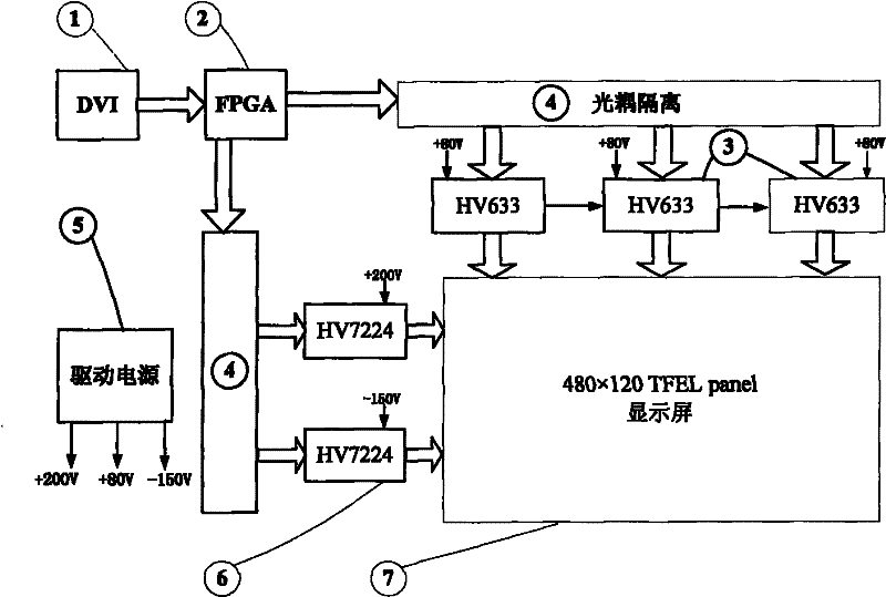
[0030] Embodiment one: if figure 1 As shown, the thin film electroluminescent display driver includes a DVI transmission circuit 1 and an FPGA controller 2, and is characterized in that the video signal is connected to the FPGA controller 2 through the DVI transmission circuit 1, and the two outputs of the FPGA controller 2 After the optocoupler circuit isolation module 4, it is respectively connected to a TFEL display screen 7 of thin film electroluminescence material through the row driver chip 6 and the column driver chip 3, and a driving power module 5 provides working power for each group of devices. The FPGA controller 2 receives the DVI signal 1 and outputs the TFEL control signal, controls the row 6 column 3 driver chips after isolation by the photocoupler 4, and outputs high voltage alternately at different times of the positive and negative voltage fields to act on the TFEL screen 7, when applied When the voltage difference between the rows and columns of the TFEL sc...

Embodiment 3

[0052] Embodiment three: present embodiment is identical with embodiment two, and special point is that the software design of TFEL display driver is as follows:

[0053] The TFEL display driver software includes two parts: TFEL display driver and DVI video signal transmission software.

[0054] , TFEL display driver programming software:

[0055] In the quartus software launched by Altera Corporation, two programming languages, VHDL and Verilog HDL, are used to write the software.

[0056] 1) According to the internal structure of the row driver chip HV7224 such as Figure 9 As shown, when the data reset terminal (DRIO) is at a logic high level, the HV7224 chip will convert all internal outputs to zero. Simultaneously, the output of the conversion register begins to shift the logic high level from the least significant bit to the most significant bit. DRIO can be activated at any time. The DIR and SHIFT terminals can control the direction of data transmission. When DIR is...


PUM


Abstract

The invention relates to a film electroluminescence display driver which comprises a DVI transmission circuit and an FPGA controller. Video signals are connected to the FPGA controller through the DVI transmission circuit, two ways of output of the FPGA controller are respectively connected to a film electroluminescence display through a line drive chip and a column drive chip after passing through an optical coupling circuit separation module, and a drive power module supplies a work power supply to each component device. The invention receives digital video signals which are received, calculated and sent by the DVI, the digital video signals are in image processing by the FPGA, and the FPGA generates a control time sequence to control the line drive chip and the column drive chip so as to enable the line drive chip and the column drive chip to output different drive voltages at different pixel point positions, thereby enabling different pixel points to emit lights with different intensities, therefore, images are displayed on a TFEL screen. A drive circuit drives the TFEL screen with a 120*480 lattice so as to realize 128 level gray scale display with the scanning frequency achieving 100Hz.

Description

technical field [0001] The invention relates to a thin film electroluminescent (TFEL) display driver. Background technique [0002] At present, the displays that can be seen on the market include cathode ray tube CRT display, liquid crystal display LCD and plasma display PDP. The disadvantage of CRT is that the maximum size is only 38 inches, bulky and bulky, power consumption, environment and safety are not very ideal. However, both LCD (especially active matrix thin film transistor LCD) and PDP have disadvantages such as high price, huge investment, complicated process and difficult manufacture. LCD also has problems such as small viewing angle and low response speed. [0003] In response to the above problems, scientists and engineers have developed a series of novel flat panel display technologies that can overcome the above shortcomings and combine their respective advantages after years of exploration. This is the electroluminescent display ELD (Electroluminescent D...

Claims


Application Information

Patent Timeline
Patent Type & Authority Applications(China)
IPC IPC(8): G09G3/30G09G3/32G09G3/3258
Inventor 冉峰黄舒平杨晓徐美华杨辉
Owner SHANGHAI UNIV
Learn More