
Overvoltage protection element and manufacturing method thereof

A technology for protecting components and manufacturing methods, applied in electrical components, emergency protection circuit devices for limiting overcurrent/overvoltage, emergency protection circuit devices, etc., can solve the inconvenience, general products and methods do not have suitable structures and methods , Overvoltage protection components with reduced withstand voltage stability and other issues, to achieve the effect of optimal product characteristics

Inactive Publication Date: 2012-05-30
CYNTEC
View PDF3 Cites 1 Cited by
  • Summary
  • Abstract
  • Description
  • Claims
  • Application Information

AI Technical Summary

Problems solved by technology

However, the method of making the gap by diamond blade cutting or laser cutting may easily cause burrs or protrusions on the end surface of the metal electrode, which will affect the roughness of the end surface of the metal electrode and reduce the withstand voltage stability of the overvoltage protection element.
[0006] It can be seen that the above-mentioned existing overvoltage protection element obviously still has inconvenience and defects in product structure, manufacturing method and use, and needs to be further improved urgently.
In order to solve the above-mentioned problems, the relevant manufacturers have tried their best to find a solution, but no suitable design has been developed for a long time, and there is no suitable structure and method for general products and methods to solve the above-mentioned problems. This is obviously a problem that relevant industry players are eager to solve

Method used


Image

  • Overvoltage protection element and manufacturing method thereof
  • Overvoltage protection element and manufacturing method thereof
  • Overvoltage protection element and manufacturing method thereof

Examples


Embodiment Construction

[0072] In order to further explain the technical means and effects that the present invention adopts to achieve the intended purpose of the invention, below in conjunction with the accompanying drawings and preferred embodiments, the specific implementation, structure, The manufacturing method, steps, features and effects thereof are described in detail below.

[0073] Some embodiments of the present invention will be described in detail as follows. However, in addition to the following description, the present invention can also be widely implemented in other embodiments, and the scope of the present invention is not limited by the embodiments, which should be determined by the claims. Furthermore, in order to provide a clearer description and a better understanding of the present invention, various parts in the drawings have not been drawn according to their relative sizes, and some dimensions have been exaggerated compared with other relevant dimensions; irrelevant details ...


PUM


Abstract

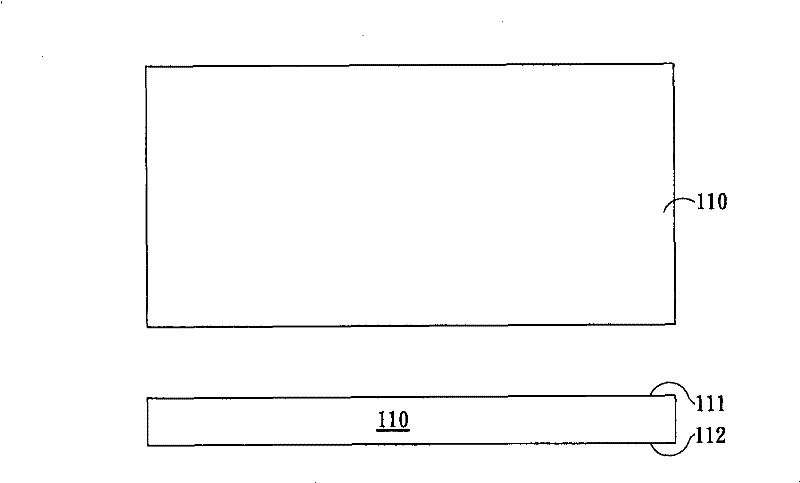
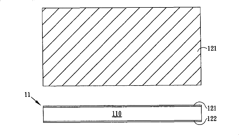
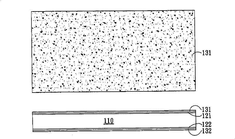
The invention relates to an overvoltage protection element and a manufacturing method thereof. The overvoltage protection element comprises a basal plate and a pair of electrode layers, wherein a clearance is arranged between electrode layers, a shade layer is arranged above the clearance and part of the electrode layers, and the shade layer and the clearance are covered by a sealing layer. The invention also provides the manufacturing method of the overvoltage protection element, which comprises the following steps: providing the basal plate; forming a first light obstruction layer on the basal plate; forming a patterning metal layer on the first light obstruction layer; taking the patterning metal layer as an exposure light cover and exposing and developing the first light obstruction layer so as to expose part of the basal plate; removing the patterning metal layer; forming a pair of electrode layers on the exposed basal plate, wherein the clearance is arranged between the electrode layers; and forming the sealing layer covering the clearance. The metal electrodes of the invention have end faces with better verticality, and the condition that substances except for air is remained in the clearance between the two metal electrodes can be effectively avoided so as to obtain a better product property, so that the invention is more suitable for practical use.

Description

technical field [0001] The invention relates to a passive element, in particular to an overvoltage protection element and a manufacturing method thereof. Background technique [0002] Over-Voltage Protecting Device (Over-Voltage Protecting Device) is widely used in various electronic system products and electronic communication equipment, so as to avoid damage to electronic equipment due to abnormal voltage or Electro-Static Discharge (ESD). Generally, the overvoltage protection element is connected in parallel to the power supply. When the overvoltage protection element does not work, the overvoltage protection element has a considerable resistance and hardly affects the original circuit; when the voltage is greater than the critical voltage of the overvoltage protection element, The resistance of the overvoltage protection element will drop rapidly, leading the overvoltage to the ground terminal of the power supply, so as to prevent other electronic components from being d...

Claims


Application Information

Patent Timeline
Patent Type & Authority Patents(China)
IPC IPC(8): H02H9/06H01T4/12
Inventor 王钟雄林鸿铭陈国枢罗文翔
Owner CYNTEC
Learn More