Voltage balancing device and method of battery system, and electric equipment

A battery system and voltage balancing technology, applied in battery circuit devices, circuit devices, collectors, etc., can solve the problems of low energy utilization, low efficiency of balance, limited heat dissipation capacity, etc., to improve energy utilization and improve Effect of Voltage Balance Efficiency

Inactive Publication Date: 2010-06-23
HUAWEI DEVICE (SHENZHEN) CO LTD
View PDF0 Cites 11 Cited by
  • Summary
  • Abstract
  • Description
  • Claims
  • Application Information

AI Technical Summary

Problems solved by technology

[0008] figure 1 The voltage balancing device shown uses a passive method to balance the voltage on each single battery cell. The excess energy (the single battery cell with high voltage stores excess energy) is consumed in the form of heat through the balancing resistor R, and the energy utilization rate is low.
In addition, because resistors, switches, and voltage balance adjustment circuits are generally integrated in a dedicated control chip to save board area, the balance current generally does not exceed 100mA due to the limitation of the heat dissipation capability of the control chip. For a battery system with a large capacity, the time required for the entire process of balancing the voltage may be as long as 8 hours or even longer, and the efficiency of the balance is low

Method used


Image

  • Voltage balancing device and method of battery system, and electric equipment
  • Voltage balancing device and method of battery system, and electric equipment
  • Voltage balancing device and method of battery system, and electric equipment

Examples


Embodiment 1

[0073] It should be noted that, in the first embodiment, the battery system is composed of three single cells connected in series. in particular:

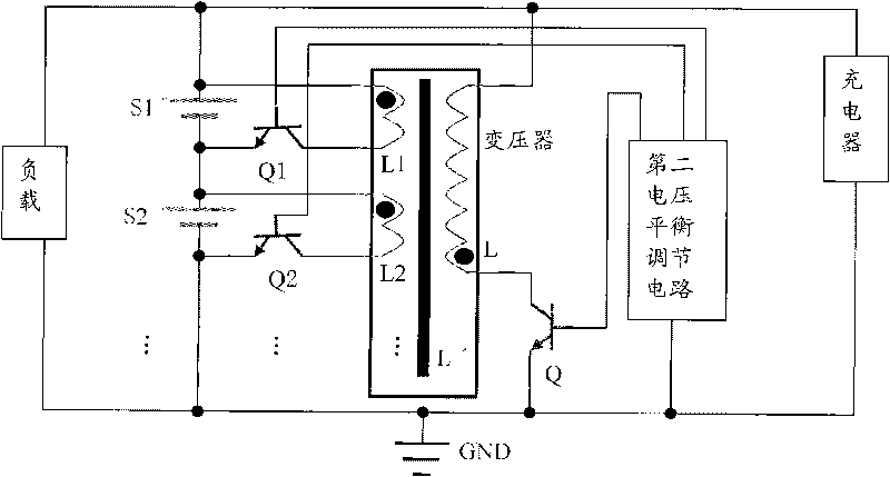
[0074] like Figure 4 As shown, the voltage balancing device of the battery system in the embodiment of the present invention includes: a transformer, the transformer includes a primary winding L, a magnetic core L' and three secondary windings L1, L2, L3, the primary winding L and three secondary windings The primary windings L1, L2, and L3 are all wound on the magnetic core L'; the primary switch Q, the primary switch Q is connected in series with the primary winding L, and is connected in parallel with the primary winding L to the battery system; the three secondary switches Q1, Q2, Q3, each secondary switch is connected in series with a secondary winding (for example, secondary switch Q1 is connected in series with secondary winding L1, secondary switch Q2 is connected in series with secondary winding L2, secondary switch Q3 i...

Embodiment 2

[0091] Embodiment 2 of the present invention also provides a voltage balance device for the battery system. The voltage balance device for the battery system in Embodiment 2 is basically the same as the voltage balance device for the battery system in Embodiment 1, the difference lies in the Second, the voltage balance during the discharge process. in particular:

[0092] 1) Balance during charging

[0093] The charging process is the same as that in the first embodiment.

[0094] 2) Balance during discharge

[0095] When the battery system discharges the load, the voltage balance regulation circuit first controls the disconnection of the primary switch Q and all the secondary switches Q1, Q2, Q3, and then detects the voltage on each single cell S1, S2, S3 at all times, when found When the voltage of one of the single cells (such as the single cell S3 ) is lower than the voltage of the other single cells, the discharge balancing process is started.

[0096] First, the volt...

Embodiment 3

[0100] like Figure 7 As shown, Embodiment 3 of the present invention also provides a voltage balancing device for a battery system. It should be noted that the voltage balancing device of the battery system in the third embodiment is basically the same as the voltage balancing device of the battery system in the first embodiment, except that the second voltage balancing regulation current is used to control the battery The voltage balance of the system during the charging process and the discharging process. in particular:

[0101] 1) Balance during charging

[0102] When the charger is charging the battery system, the voltage balance regulation circuit first controls to turn off the primary switch Q and all the secondary switches Q1, Q2, Q3, and then detects the voltage on each single cell S1, S2, S3 at all times , when it is found that the voltage of one of the single cells (such as the single cell S3 ) is higher than the voltage on the other single cells, the charge bal...


PUM


Abstract

The invention discloses voltage balancing device and method of a battery system, and electric equipment, which relate to the technical field of batteries and are invented for improving the energy utilization ratio and the voltage balancing efficiency of the battery system. The voltage balancing device of the battery system comprises a transformer, a primary switch, at least two secondary switches and a first voltage balance regulating circuit, wherein the transformer comprises a primary winding and at least two secondary windings; the first voltage balance regulating circuit is used for detecting the voltage of each single electric core of the battery system, controlling the closing of the primary switch when the battery system is charged and controlling the closing of the secondary switches connected in parallel with the single electric core with the lowest voltage while opening the primary switch after set time. The invention can be used for balancing the voltage of each single electric core in the battery system.

Description

technical field [0001] The invention relates to the technical field of batteries, in particular to a voltage balancing device, method and electrical equipment for a battery system. Background technique [0002] The common feature of the commonly used rechargeable batteries at present is that the voltage of a single cell is relatively low. V. In some electrical equipment, it is necessary to use a battery system formed by connecting multiple cells of the same type in series to realize power supply. For example, on a notebook computer, three lithium-ion cells can be connected in series to form an 11.1V battery system, or four lithium-ion cells can be connected in series to form a 14.8V battery system. [0003] In such a battery system, due to the differences in the electrical characteristics of each individual cell, the voltage on each individual cell connected in series will be different. For example, during the charging and discharging process, the voltage on a single cell ...

Claims


Application Information

Patent Timeline
Patent Type & Authority Applications(China)
IPC IPC(8): H02J7/00H01M10/42
CPCY02E60/12Y02E60/10
Inventor 郭祖峰
Owner HUAWEI DEVICE (SHENZHEN) CO LTD
Why Eureka
Try Eureka